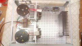
Better equalize the tail current between channels via different value R3. Lower in this case to come up. And maybe replace that particular LSK170 with that break out tendency if it keeps doing it no matter what.
I agree. The left channel stubbornly refuses to oscillate. I'm thinking there may be an outright defect in a component. I'd say the odds are close to 100% if I build up another of these boards I won't see this problem again.
I tried to look for oscillation in the regulator, but didn't find anything conclusive. The 13MHz tends to pollute everything once it starts, so it's hard to determine the source. Between the regs and the signal circuitry there's a heck of a lot of gain on that breadboard.
I tried to look for oscillation in the regulator, but didn't find anything conclusive. The 13MHz tends to pollute everything once it starts, so it's hard to determine the source. Between the regs and the signal circuitry there's a heck of a lot of gain on that breadboard.
I cut the gate traces right next to the input devices and installed 100 Ohm 0805 SMD resistors. I was surprised as heck that this made the oscillation much worse. It seems like I can can damp it out entirely by the judicious application of my finger.
I think the problem is my layout. I think there's capacitive coupling from the output stage to the gate of J2 and that's the issue. I might be able to disconnect the suspect trace tomorrow. We'll see.
This is great entertainment. Much more fun than politics.
I think the problem is my layout. I think there's capacitive coupling from the output stage to the gate of J2 and that's the issue. I might be able to disconnect the suspect trace tomorrow. We'll see.
This is great entertainment. Much more fun than politics.
Oh yes my friend. But i setup the other stuff box-Psu orientation.... etc.... until come the boards from Mike.
Last edited:
Salas, about deciding the size of ubibs R1 resistors when feeding DCG-3 (double ubibs)
I have 150mA bias, so:
for negative boards 150mA+100mA= 250mA (R1=2.4 ohm)
For positive boards 300mA+100mA= 400mA (R1=1.5 ohm)
Is this correct?
I have huge sinks ( a-class amp case), so heat will not be problem.
What size transformers I need? Maybe 2x 60VA 2x18V outputs?
(Toroidy supreme audio v2 are tempting me)
Current limit figures are correct. Including low impedance headphones use. If for line duty only you could use 250mA limit all around and save on heat wasted energy.
The VA and model you mentioned make an excellent tranformers choice.
The VA and model you mentioned make an excellent tranformers choice.
Thanks again
What you think about Jantzen 5w superes for R1?
What would be the best resistor for this position?
What you think about Jantzen 5w superes for R1?
What would be the best resistor for this position?
First of all you don't need such Wattage R1 resistors for this current limit region in UBiB 1.3 PSUs. 1W is plenty so your choices widen a lot. You may also put low ppm metal films.
(Toroidy supreme audio v2 are tempting me)
I too went for the supreme audio transformer (for my cherished but unfinished B1). They are very good. But they‘re very big too, you may want to make sure they fit into your design.
Apologies for my chattering but I couldn’t resist and maybe you will be glad to have this reminder...
Thanks Salas and myleftear for your input. Im still having a hard time finding good resistors under 2r (1W or 2W).
If I dont find something suitable at that range, I think Im going to use Mills wirewound ( ayrton perry, non magnetic) 5W.
If I dont find something suitable at that range, I think Im going to use Mills wirewound ( ayrton perry, non magnetic) 5W.
Mills are very good. I put flexible footprint at the UBiB R1 area so you can use practical to find parts within reasonable size. Not that a higher Watt part is a problem, just not necessary in moderate mA settings cases where you can still find smaller/cheaper.
Most smaller ones stop availability at 10R. There are exceptions like the Takman REY75 1W list bottoming out at 2.2R for instance. For 1.5R it would take two in parallel i.e. 3R//3R.
Most smaller ones stop availability at 10R. There are exceptions like the Takman REY75 1W list bottoming out at 2.2R for instance. For 1.5R it would take two in parallel i.e. 3R//3R.
Of course in the olden days we would wind our own 1 ohm resistors with some nichrome wire (still available) wound around a 100 ohm 1W or 2W resistor.
- Home
- Source & Line
- Analog Line Level
- Salas DCG3 preamp (line & headphone)
