Casual. Mostly tastes comming from very old magazine La revue de l'Audiophile, then La Nouvelle Revue du Son... with many experiments from enthusiasts engineers, manufacterers : Focal, Hiraga and so on till JMLC. The love of high efficienty, so horns etc, came from review of visits in Japan and USA. Hiraga for instance is half french half japonese, there was no equivalent review in USA that opened a huge windows towards the crazy diy experiments that japoneeses enthusiasts did with all that tubes & radio americans exported there during the japoneese economy reconstruction after the WWII. It's understandable as France has not the size of the american commercial markett. The acoustic guys there in Europe are mostly working for naval, aerospace, car industries or concrete makers in the building domain and vibration analysis I believe. Hifi in France is more a top niche markett than in USA. Despite movies venues helped a lot in France. And btw you can see it, audio industries are often powerfull in coutries where there is a movie culture like USA, France, Italy, Great-Britain... not only of course, but that helped a lot. And we kow fr where it comes, even if audio industrie pre existed in Europe and in France in particular.
It partially explains why France was enthusiast with horns more than most of the european countries as Great-Britain for instance.
It partially explains why France was enthusiast with horns more than most of the european countries as Great-Britain for instance.
Last edited:
Putting a "non-scientific" study on the same footing as the work of Toole and Olive is a false narrative.
Agreed, but that's not the case in my previous post.
In reference to the comment made earlier about standouts on audio shows, these rare diamonds are often the fruits of people with a personal vision. I am thinking of Bert Doppenberg and Basil Martion, among others
The scientific work is especially important for mass production of a verifiably high level. This applies to Harman products and a whole bunch of similar high-end manufacturers.
You yourself have indicated that there is a difference between the pursuit of a faithful reproduction of a studio recording and reproduction of a life event.
Some people are very happy with a Genelec or Neumann monitor system. I understand that and such a system is handy to have on hand, as a reference.
My personal quest is something bigger, with the science in mind, but according to personal preferences. This a diy forum after all.
Last edited:
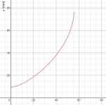
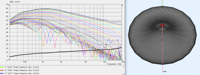
I've made a Vituix DI calculation from an IB ABEC sim of an axisymmetric guide (based on my attempt at reverse engineering a curve similar to the one mabat showed in the DE7 guide). It's not as well optimised but the general smoothness is there. The early reflections DI is really quite flat but not particularly high, standard DI is gradually rising.

Attachments
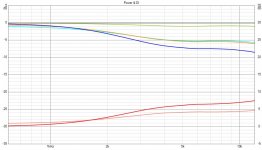
The PIR was in the other graph but it is virtually identical to the early reflections curve. Is this what you wanted to see?
Attachments
Last edited:
This should be done for free field conditions because this is what the waveguide was really designed for - it will have a higher DI at lower frequencies when free standing than in the infinite baffle, so the rise will be even more gradual (I would say considerably).I've made a Vituix DI calculation from an IB ABEC sim of an axisymmetric guide (based on my attempt at reverse engineering a curve similar to the one mabat showed in the DE7 guide). ...
I'll try to implement the DI calculation directly into the sims/VACS and show you.
Yes of course, I was aiming for a freestanding guide but the rollback didn't work the way I thought it would so it made getting a similar curve via Ath much less predictable (which you mention in the instructions). The above solved in 13 seconds and I thought still looked pretty good for a 6" guide.This should be done for free field conditions because this is what the waveguide was really designed for - it will have a higher DI at lower frequencies when free standing than in the infinite baffle, so the rise will be even more gradual (I would say considerably).
That would be great, I find the translation of Nils document to English through Google difficult to understand.I'll try to implement the DI calculation directly into the sims/VACS and show you.
Interesting software and concept," I think " As I cant really tell yet.
You see I am still wading through piles of assorted errors.
However I am really,really looking forward to getting this running.
You see I am still wading through piles of assorted errors.
However I am really,really looking forward to getting this running.
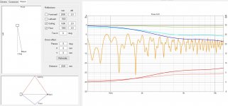
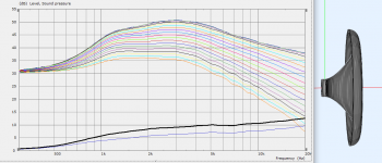
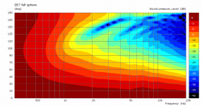
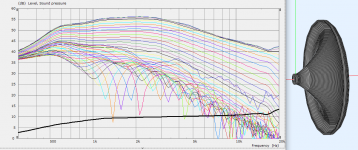
Here we go - the small "DE7" waveguide (7.7"), DI for the axial response. The black DI curve is full space (i.e. the real DI), the blue curve for the front hemisphere only (just for comparison). In the bode plot only polars up to 90 deg are shown.That would be great, I find the translation of Nils document to English through Google difficult to understand.
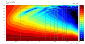
Polar map normalized to 0 deg.
Attachments
Last edited:
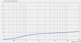
This is for the response at 15 deg off-axis ("listening window" approximation).
Attachments
Last edited:
Mabat, I just want to tell you that i agree that the development of some target/evaluation criteria is really the frontier of the field as the waveguide modelling software has now become sufficiently advanced. It is important that the underlying theortical discussion does not get lost among the practical implimentation challenges, such as direct DI curve integration.
A point to the subject of slightly increasing DI versus flat flat DI; is there any wheighting of angular measurements as they represent an increasinly larger area on the "measuremt hemisphere"? That is a factor that really accelerates the importance of what might seem like subtle response curve differences in the plots. Especially with the quite axisymmetric fairly wide beamwidth devices (90 ish degree) most if us are interested in.
I belive mr Geddes has done some work on this.
The more i think about this topic the more significant it seems.
Last edited:
Of course they have different weights in the calculation, proportionately to the area they represent, that's the essence of it. The beauty of axial symmetry is that this can be calculated very easily just from one set of polars.is there any wheighting of angular measurements as they represent an increasinly larger area on the "measuremt hemisphere"?
The PIR was in the other graph but it is virtually identical to the early reflections curve. Is this what you wanted to see?
Yes, thank you.
#4093 does the whole sphere - right? Now if you are bored and have nothing to do 🙂 - could you just keep the rollover rolling to close the "ball"? That would I think be interesting to see. I would assume that the driver would fit inside such an extension... but I can really see why you wouldn't bother.
//
//
- Home
- Loudspeakers
- Multi-Way
- Acoustic Horn Design – The Easy Way (Ath4)