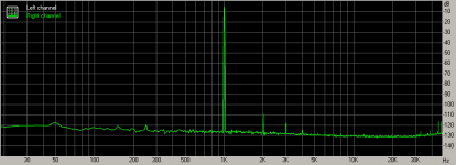
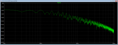
50/60Hz noise is always clearly seen on spectrums (because we are surrounded by it). It's level only changes. On this your spectrum it is quite good (a 100 dB lower than a signal level). But I suspect you may have it lower if you will use a better-screened cable from amp to soundcard. I use self-made with RG58 or RG59 (50 or 75 Ohm - it doesn't matter here).
Look at how large a difference between bad and good cable can be (it is the same amp, but measurements are made at different modes, so look at 50 Hs noise level only):
1) -85 dB 50 Hz noise level

2) almost -120 dB 50 Hz noise level

Look at how large a difference between bad and good cable can be (it is the same amp, but measurements are made at different modes, so look at 50 Hs noise level only):
1) -85 dB 50 Hz noise level
2) almost -120 dB 50 Hz noise level
Attachments
Last edited:
The 150, 250, etc is exactly what is expected from rectification: the odd harmonics in the ripple.
I think we have a Ripple Frequency (for 50Hz walls, full wave: 100Hz), plus "all" harmonics of that (100, 200, 300, 400, 500, 600, 700, 800...).
Attachments
Yes.The sound of a power supply is quite low in this spectrum. It is low itself and low comparable to signal harmonics. So I think the power supply is not the weakest part of this setup.
The diodes and PSU story is certainly not the issue.
The important point is that, the published spectrum is from a measurement at an amplifier, at it's output, I presume.
From an engineer's point of view, it is non sense to elaborate from this about the PSU.
It is a long way to find out wether it relates to the PSU itself, then transformer windings and diodes.
I personally have enough of graphs, charts and measurements dumped from nowhere without the full context.
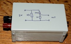
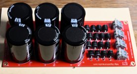
My measurement setup on picture is before I made an interface box for it. So I have a very short wire from speaker out to box and then a standard screen RCA cable from box to sound card and then a RCA cable from sound card back to amp.
All voltage gain in my power amp is done via a small interstage transformer. It has a x1 buffer in front and a PP Mosfet output stage which are source followers. The interstage transformer is very hum sensitive so by screening it with mu-metal and by using a screened power transformer and have a long distance from transformer to amp-board the 50 Hz noise was reduced significantly.
Now there was a suggestion to make the measurement interface setup balanced so speaker out is converted to balanced so XLR input on soundcard can be used. It must be a development for the future.....
The box has developed since as I can change the output level using a small pot. The Focusrite can take quite a large signal in. So for my measurement around 1 - 5W output power Focusrite can take the full speaker out signal. I have also grounded the box.
Attachments

Another change in my setup is that now I have re-generated regulated 230 VAC mains. My 230 VAC power is shown in picture before and after regulation. It stays stable at 230.6 VAC -+ 0.1 V. This makes it easier to check if my rails goes up or down by switching to like say....the SiC to standard diodes where there was a significant difference. Now I expect rails to go further up when I get the low voltage drop Schottky diodes installed. Then I will waste less energy in the PSU and I hope noise will go down a bit. At least I expect to learn "by doing stuff". There is also a picture of my DC-trap which will be installed later in front of the AC mains regulator.
Attachments
I think we have a Ripple Frequency (for 50Hz walls, full wave: 100Hz), plus "all" harmonics of that (100, 200, 300, 400, 500, 600, 700, 800...).
Actually it appears that a sawtooth, like the ripple voltage on a rectified supply capacitor, has both odd and even harmonics.
Jan
Attachments
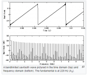
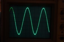
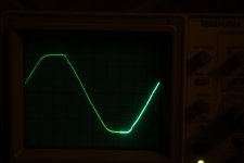
Indeed, the ripple looks like a sawtooth.Actually it appears that a sawtooth, like the ripple voltage on a rectified supply capacitor, has both odd and even harmonics.
The other way, the fast edge on the left, the slow edge on the right.
The sawtooth is a 120Hz signal in the US, 100 Hz on the other side of the bond.
It does have odd and even harmonics of 100 Hz. Even ones are at 200, 400, 600, while odd ones are at 300, 500, 700,
These are even harmonics of 50Hz, there is no odd harmonics of 50Hz.
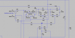
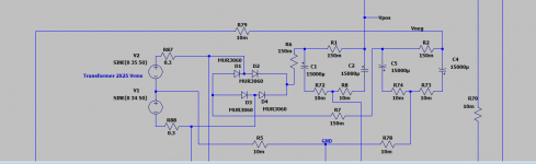
Here is also a LTspice simulation of a PS with bridge rectification.
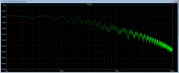
In the FFT of the Positive side, only 100 Hz harmonics are shown.
https://www.diyaudio.com/forums/pow...0-hz-350-hz-noise-linear-psu.html#post6394991
In the FFT of the Positive side, only 100 Hz harmonics are shown.
https://www.diyaudio.com/forums/pow...0-hz-350-hz-noise-linear-psu.html#post6394991
At first photo a signal wire is really short (and doesn't need any improvement). But I can't say anything about you current setup with a box (but if it is as short as first - it has to be ok too.)My measurement setup on picture is before I made an interface box for it. So I have a very short wire from speaker out to box and then a standard screen RCA cable from box to sound card and then a RCA cable from sound card back to amp.
All voltage gain in my power amp is done via a small interstage transformer. .
If you have a signal transformer then it is ok to have quite high 50 Hz noise level onto a spectrum. Minus 100 dB (at 50 Hz) is quite good for such a transformer setup (as for me).
Distorted mains voltage means added higher harmonics into a mains voltage. That means latter:
1) When rectified they are still multiple of 100 Hz.
2) The higher from 100 Hz they are (up to several kHz) - the easier to filter them.
So visually distorted mains voltage doesn't really distort amp power supply voltage at low frequencies (I mean 50 Hz ... 1 kHz range).
Last edited:
Here is also a LTspice simulation of a PS with bridge rectification.
In the FFT of the Positive side, only 100 Hz harmonics are shown.
https://www.diyaudio.com/forums/pow...0-hz-350-hz-noise-linear-psu.html#post6394991
Can you make the same simulation but add one more diode in series with another in a bridge (to simulate non-equality of rectifireing diodes)?
Last edited:
Nice way to illustrate, 150 Hz/ 250 Hz/ 350 Hz noise.
Instead or adding a diode, adding a very small resistor is enough to see the effect.
Diodes in LTSpice simulations are perfectly matched. They have, exactly the same Vf and dynamic resistance.
Instead or adding a diode, adding a very small resistor is enough to see the effect.
Diodes in LTSpice simulations are perfectly matched. They have, exactly the same Vf and dynamic resistance.
Thank you very much!
Now we clearly see an evidence of everything was said earlier. 50 Hz multiples can appear with a large level, but only if there is a significant large non-equality.
Of cause, with a lower non-equality the 50 Hz multiples level will be lower proportionally.
Now we clearly see an evidence of everything was said earlier. 50 Hz multiples can appear with a large level, but only if there is a significant large non-equality.
Of cause, with a lower non-equality the 50 Hz multiples level will be lower proportionally.
Last edited:
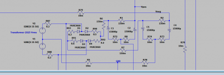
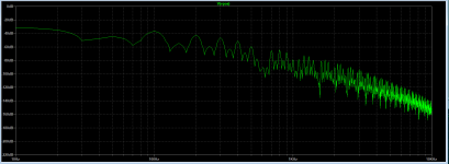
I'm not sure if I can ask you one more simulation, with non-equal voltage sources (but norm. bridge)? For example, 34 VAC and 35 VAC (as it can possibly be in a real life?Here are the results with a double diode instead of one.
The FFT is full of 50 Hz harmonics
I assume that I see an effect when I switch to the new oversized double Schottky diode bridges:
https://ixapps.ixys.com/DataSheet/L132.pdf
Diodes will be a the low and of the Vf curve and a small percentage difference between the diodes will give a small dVf difference. When I test them using a diode tester which use very little current they measure Vf between 0.068 - 0.069 V on every single diode. This is just to test that they work.
My 2 x 18V output of my transformers are very exact. As it is 400VA transformers they are closer to 2 x 19V.
I have written a mail to IXYS and asked if it is good practice to parallel the two diodes. I also asked if they are on same silicon.....just to be sure.
To know precisely how equal they are: With nothing hooked to the secondaries, connect them in series and measure the AC voltage accross the ends. You'll get double the voltage or a near zero voltage.My 2 x 18V output of my transformers are very exact. As it is 400VA transformers they are closer to 2 x 19V
The near zero voltage gives you an accurate measurement of V1 - V2.
Of course.
Thanks for the simulations.
To go beyond this study one could look at the sensitivity of the various imbalances.
This to answer questions like, what is more or less important
matching secondary winding voltage
matching diode Vf
matching diode dynamic resistance.
matching wiring resistance.
An academic study would give:
A plot of noise versus voltage imbalance.
A plot of noise versus resistance imbalance.
With a clear definition of what is the considered noise.
I think it should be the RMS value of the 50 Hz odd harmonics.
Are they other imbalances that matter ? Diode speed recovery for instance.
- Home
- Amplifiers
- Power Supplies
- 150 Hz / 250 Hz / 350 Hz noise in linear PSU