I have relative large C in my CRCLC filter (5 x 33 mF) for each bridge in total so I expect large current peaks.
The SiC I used was 14-15A rated in TO220 but I got problems with unstable Vf.
The standard 35A bridges are very stable but has more noise than the SiC's.
The PCB (Universal PCB from DiYAudio Store) has easy mount for TO-247 and the layout will parallel the two diodes in a TO-247 package with 3 legs.....without need for any bending of the legs. And the TO-247's is on the way to me.......
But you are right....they are relative expensive......
It is also a bit of technical interest I do this. Also to see how low a voltage drop that is possible.

Larger caps only make larger charging spikes at start up, then they are the same, only depending of the load and caps ESR.
Is paralleling diodes a common DiYAudio practice ?
Is paralleling diodes a common DiYAudio practice ?
If all 3-leg TO-247 devices are dual-diodes then I think it is. The universal PSU PCB connects pin 1 and 3 together:
diyAudio Power Supply Circuit Board v3 illustrated build guide
....but if 3 leg TO-247 exists with only one diode with anode connected to either pin 1 or 3 then I may be wrong.
My assumption was that the two diodes in a TO-247 package was made on same silicon and therefor very identical so it is ok to parallel these. I tried to find any information on this in the data sheet. But at least I could not find any warning against it?
If the two diodes share the current equally then I will get 1/2 Vf if data sheet specifies Vf pr. diode?
No.If the two diodes share the current equally then I will get 1/2 Vf if data sheet specifies Vf pr. diode?
I would be interested to see if the current sharing is exactly the same ( in practice ) --if not then there can be other problems .
The 150, 250 Hz (and 50 Hz) noise is induced into a circuit (a rectifire don't make it), and signalize not perfect wireing.
The 150, 250, etc is exactly what is expected from rectification: the odd harmonics in the ripple.
Jan
I do not agree ( or I do not understand).
If the two half waves are identically rectified, there is no odd harmonics. The frequency of the rectified signal is 100Hz. The fundamental is 100Hz, the harmonics, 200, 300, 400, 500,
If the two half waves are identically rectified, there is no odd harmonics. The frequency of the rectified signal is 100Hz. The fundamental is 100Hz, the harmonics, 200, 300, 400, 500,
Last edited:
No. There is only even harmonics in a ripple voltage (100/120 Hz, then 200/240 Hz, 300/360Hz etc).The 150, 250, etc is exactly what is expected from rectification: the odd harmonics in the ripple.Jan
Possibly if we talk about bi-polar (+,0,-) voltage then odd harmonics can appear somewhere (maybe not equal secondary voltages?).
I almost sure they are in a same die (99.9%). I haven't heard it was done in other way.We need one to crack open this diode pair to see if the diodes are in a same die.
There is no need to break up a good part to find a source of an odd harmonics because TS is a beginner (a newbie) (I'm sorry for saying this) so this is a main reason he has not ideal power supply.
Last edited:
Good.
Now we need one who knows well, solid state physics and manufacturing processes to enlighten about how close the two diodes on the same die do match.
Perhaps, making diodes by paralleling pairs, is a worthwhile way to obtain a set of better matching diodes.
Each pair provides a diode Vf that is an average of the two individual Vfs.
We are talking diodes here exactly what I brought up in post #4 ?
If so diodes aren't perfect especially the standard type ( non switching ) .
The rectification action changes the sine wave and adds new frequencies the current passing through the diode is a function of the voltage -higher voltage =higher harmonic distortion as larger amounts of current are being blocked by the diode .
Yes even harmonics are the highest but to say--no odd harmonics is not dealing with reality .
Dont take my word here there are plenty of online university Papers on it, I put it in very simple terms but if you read up on diode design and function relating to harmonics and look at the maths you will see what I mean.
I can send a mail to IXYS and ask how these are manufactured and if running the diodes in parallel is a good idea.
I repeat:Yes even harmonics are the highest but to say--no odd harmonics is not dealing with reality .
If the two half waves are identically rectified, there is no odd harmonics. The frequency of the rectified signal is 100Hz. The fundamental is 100Hz, the harmonics, 200, 300, 400, 500.
What is your point ?Dont take my word here there are plenty of online university Papers on it, I put it in very simple terms but if you read up on diode design and function relating to harmonics and look at the maths you will see what I mean.
I am simply refering to basic Fourier maths.
If you are referring to Fourier then I should have provided a link to a Fourier graph/trace showing a trace of harmonics in a "perfect " diode , its full of harmonics .
Diodes aren't perfect especially power diodes.
Diodes aren't perfect especially power diodes.
A practice says that a large amount of odd harmonics in rectified voltage appear only if there is some significant difference in diodes or secondary voltages. Or just not perfect wiring. So there is no need to make scientific debates here.
Of cause, there is always some amount of odd harmonics in rectified voltage but their level is much less (an order at least or more) than a level of even harmonics.
If a level of odd harmonics is the same as even harmonics (as we see here) - that is not caused by a bit non-equal diodes.
Of cause, there is always some amount of odd harmonics in rectified voltage but their level is much less (an order at least or more) than a level of even harmonics.
If a level of odd harmonics is the same as even harmonics (as we see here) - that is not caused by a bit non-equal diodes.
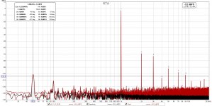
Here is a distortion measurement from the time where the SiC 600V, 14-15A diodes was installed (TO-220, 2-leg, single diodes).
Since then I have made improvements to get the 50 Hz peak lower and and a few other "improvements".....
Interesting discussion about odd harmonics.....I learn something every day!
From distortion measurement it can be seen that odd harmonics was less at that time.
I hope I can get that low again using the TO-247 Schottky. I will be satisfied if this is possible together with the much lower 50Hz peak I have now.
Attachments
- Home
- Amplifiers
- Power Supplies
- 150 Hz / 250 Hz / 350 Hz noise in linear PSU