Any reason not to use a short piece of bulk balanced mic cable for the amp board to XLR connection?
This Mogami "star quad", for example, looks pretty nice and can be bought for $2/ft.
This Mogami "star quad", for example, looks pretty nice and can be bought for $2/ft.
You should use the pure solid core copper, twisted pair - unshielded. The shield, coming from the XLR connector, should be connected to amp chassis right at the connector (pin 1), using the same screw used to mount the XLR connector to the backplane. You could even use the ground lift at this point: DC coupled using very short wire, OR AC coupled using 0.1uF disc ceramic cap (ground lift). This will drastically reduce the noise pickup loop length.
The amp PCB's will still get the ground reference connection from the power supply board common... and... the slight buzz that many have reported will be completely absent.
Unfortunately, with a single-ended input, this can not be done... so a ground-break resistor could be used.
The amp PCB's will still get the ground reference connection from the power supply board common... and... the slight buzz that many have reported will be completely absent.
Unfortunately, with a single-ended input, this can not be done... so a ground-break resistor could be used.
Last edited:
This would be my strategy. I'm pretty sure it's related to the input stage.
I would use a process of elimination:
Step 1: Replace Q2. Do not apply too much heat while soldering.
If that does not fix it:
Step 2: Replace J1 and J2 with 100 ohm gate stopper resistors.
If that does not fix it:
Step 3: Replace the two jfets with another matched pair. Once again, do not apply too much heat.
I am betting replacing Q2 is going to fix it but time will tell.
Step 1 didn't work.

You should use the pure solid core copper, twisted pair - unshielded. The shield, coming from the XLR connector, should be connected to amp chassis right at the connector (pin 1), using the same screw used to mount the XLR connector to the backplane. You could even use the ground lift at this point: DC coupled using very short wire, OR AC coupled using 0.1uF disc ceramic cap (ground lift). This will drastically reduce the noise pickup loop length.
The amp PCB's will still get the ground reference connection from the power supply board common... and... the slight buzz that many have reported will be completely absent.
OK, so if I understand correctly, does this leave the GND hole on the amp board vacant? Twisted pair running from +IN and -IN to Pins 2 and 3 on the XLR connector? If I then use a XLR-to-RCA adapter that connects pins 1 and 3, will that still work?
And for wire, solid-core twisted pair taken from Ethernet CAT5 seems popular?
I can't remember who had asked in the other thread re: CL-60 to Euroblock. Apologies.
Slightly related, I suppose.
Short wire soldered to CL-60 legs on each end. One side to Euroblock, one side to your mains earth connection to the chassis. Legs and soldered connections should be heat-shrinked. More experienced folks please chime in, but I believe if you're using wire into the Euroblocks that the strands should not be tinned together, and the CL-60 leg should not ideally be inserted directly into the Euroblock. Terminate the other end with a ring/spade or however you'd like for the chassis connection. If it's neater, and you have enough length to work with, you may just be able to add a termination directly to the leg of the CL-60 for your chassis-side connection.
OR... solder CL-60 to PSU board. Run small wire to chassis. But, I think someone mentioned for that build that you did not want to solder the CL-60 to the PSU board and wanted to use the Euroblock.
Probably lots of cool solutions, but I haven't personally seen that specific configuration either.
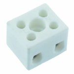
Anyone have guidance for how to attach the CL60 thermistor between PSU ground and chassis...
Use a ceramic terminal block, both legs of the CL60 in one side, two wires on the other side, one wire to chassis, the other to the PSU ground

Attachments
Use a ceramic terminal block, both legs of the CL60 in one side, two wires on the other side, one wire to chassis, the other to the PSU ground
Any reason that a plastic terminal block wouldn't do just as well for this? I've got an extra two position plastic terminal block handy.
OK, so if I understand correctly, does this leave the GND hole on the amp board vacant?
Yes.
The AMP PCB is still getting its ground reference from the power supply PCB. If you connect the speaker negative to the AMP PCB (as per the build guide instructions) -> then there will be some current (few amps if you like your music loud) running through that point as well. If you connect the speaker negative straight to the power supply common, that point will indeed serve just as a ground reference for the AMP PCB. Try both and see which one sounds better.
Twisted pair running from +IN and -IN to Pins 2 and 3 on the XLR connector?
Yes.
If I then use a XLR-to-RCA adapter that connects pins 1 and 3, will that still work?
It will, as long as you connect pin 1 to the XLR screw (to the amplifier chassis, by using the screw that fastens the XLR connector to the chassis). This wire link should be reasonably short (2-3 cm)
You could choose not to connect the shield at all if using XLR exclusively. Just leave the source-end shield connected to the source chassis (this is usually more “quiet”).
And for wire, solid-core twisted-pair taken from Ethernet CAT5 seems popular?
Yes.... solid core copper wires tend to sound better than litz (multi-strand).
There will be a huge difference in sound if you go for the solid core silver wire... you may like it. This will depend on the rest of your system as well, but it usually works really well. You will need only 1.5 – 2 meters max.
Any reason that a plastic terminal block wouldn't do just as well for this?....
In a fault condition, the CL60 will get hot, it's possible a plastic one could melt
See if R5 has the correct value and also consider replacing the 9.1V zener D1, in case it is 'noisy'.
I haven't done that yet, but help me make sense of this?
At the amp, I put the right channel XLR cable to the left channel, and the left channel XLR cable to the right channel: no change, static stayed in the right speaker.
I put it back to normal. Next:
At the amp, I put the right channel banana plugs at the left channel, and the left channel banana plugs at the right channel: the static moved to the left speaker.
I put the speaker cables back to normal, except that I switched out the right channel speaker cable with an identical but unused cable. The static sound stayed in the right channel.
Last edited:
So a new Q2 didn't fix the problem. Dang...
See if R5 has the correct value and also consider replacing the 9.1V zener D1, in case it is 'noisy'.
At the amp, I put the right channel banana plugs at the left channel, and the left channel banana plugs at the right channel: the static moved to the left speaker.
I put the speaker cables back to normal, except that I switched out the right channel speaker cable with an identical but unused cable. The static sound stayed in the right channel.
Today I added those plastic washers (from the back panel kit) to the interior side of the right channel speaker binding posts. I'm certain there's no contact, but thought it could help.
I also pulled the amp board and clipped every through-lead as close to the board as I could get and added some backside soldering to anything that wasn't perfect. There was no heatsink contact before, but I did it anyway.
No change. Still have static in the right channel that sounds like the end of a record, just spinning (same for all sources).
Question: is D1 directional?
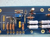
Sure is! Check the photos...
Thanks. Mine are in correctly, based on your photos.
Hey all.
Back with another question. i just powered my amp for the first time using the bulb tester and my bias on my right channel is reading 4.1v and dc offset is also reading 4.5v. any idea what may cause this? my left channel was reading algood.
Thanks Ben
Back with another question. i just powered my amp for the first time using the bulb tester and my bias on my right channel is reading 4.1v and dc offset is also reading 4.5v. any idea what may cause this? my left channel was reading algood.
Thanks Ben
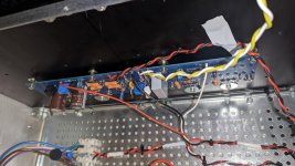
Attachments
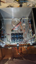
This usually means that the output MOSFETs are "floating", i.e. they are not "turned on" - they are not conducting current. Assuming the power supply rails are okay?? You are not specifying if the voltage you measured is + or - 24V DC? Also, you are not saying where you measured the voltage(s)?
Bad ground? Did you short the MOSFETs to the ground? If yes, then check the power supply rails and MOSFETs. Any smoke? (probably not because of the bulb limiter...)
Bad ground? Did you short the MOSFETs to the ground? If yes, then check the power supply rails and MOSFETs. Any smoke? (probably not because of the bulb limiter...)
Last edited:
- Home
- Amplifiers
- Pass Labs
- Aleph J illustrated build guide