Just checked the rails and i have 24v on both. there was no smoke. yes there was continuity between the mosfets and the chassis thanks to my chassis ground i had
If you are getting +24 at the binding posts, and the power supply rails are +24 and -24 V DC, the MOSFET's are not conducting current.
The MOSFET's are turned on by:
- Q4 -> current source MOSFETs (4.3V across collector and emitter of Q4)
- {Z1, Q2 and input JFETs} -> single-ended output stage MOSFETs (8.3V across R8 and 4.3V across R7)
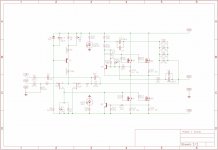
Check the original General Amplifier (Copyright 2005) schematics - it shows the voltages in question.
The second photo in this post:
https://www.diyaudio.com/forums/pass-labs/241729-aleph-illustrated-build-guide-566.html#post6402857
... shows the correct orientation of Q2, Q3 and Q4.... as well as where the links should go and the orientation of the caps. Just do a sanity check one more time.
The MOSFETs might be damaged... if they were shorted to ground. If you can not check them, just replace them all.
You did not mention if both AMP PCB's MOSFET's were shorted to the ground???
To unsolder the MOSFET's, use the Soldapult.... the trick here is to put a single drop of fine machine oil inside the tube... that will improve the suction few-folds🙂
The MOSFET's are turned on by:
- Q4 -> current source MOSFETs (4.3V across collector and emitter of Q4)
- {Z1, Q2 and input JFETs} -> single-ended output stage MOSFETs (8.3V across R8 and 4.3V across R7)
Check the original General Amplifier (Copyright 2005) schematics - it shows the voltages in question.
The second photo in this post:
https://www.diyaudio.com/forums/pass-labs/241729-aleph-illustrated-build-guide-566.html#post6402857
... shows the correct orientation of Q2, Q3 and Q4.... as well as where the links should go and the orientation of the caps. Just do a sanity check one more time.
The MOSFETs might be damaged... if they were shorted to ground. If you can not check them, just replace them all.
You did not mention if both AMP PCB's MOSFET's were shorted to the ground???
To unsolder the MOSFET's, use the Soldapult.... the trick here is to put a single drop of fine machine oil inside the tube... that will improve the suction few-folds🙂
Last edited:
thankyou. so i just checked q4 and i have about 80mv across the collecter and emitter and its dropping fairly quickly. I have 8.4v across r8 and 1.3v across r7.
The orientation of all my caps and and q2, q3 and q4 are correct.
yep it was both channels are were shorted to ground.
sweet thankyou. ill desolder them and try check them
The orientation of all my caps and and q2, q3 and q4 are correct.
yep it was both channels are were shorted to ground.
sweet thankyou. ill desolder them and try check them
OK. So I just desoldered all the irf240 mosfets and checked them all with my multimeter quickly and they all seem to be fine
Just used the diode test on my multimeter to test the ztx 450 and ztx 550 and they're fine too. Though I broke one removing it so Ill have to replace that
So to sum things up. I am still getting 24v at the speaker terminals on the channel I didn't accidentally break the ztx450 on.
I did a diode test on the other ztx450s and ztx550s and they tested fine with no shorts.
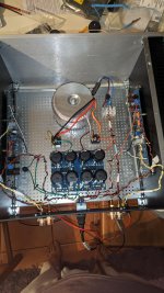
I pulled the irfp240 mosfets out and did a diode and Continuity test on all of those and they didn't show any shorts.
I got 550mv across the source and drain using the diode test function on my multimeter.
When the amp is on I get 8.4v across R8
But only 1.3v across R7
And next to nothing across R18, R19 etc..
I get 24.5v out of each channel on the Psu and 50v between v+ and v- on the amp boards.
I'm unsure if any of many of these measurements will help
I'm a bit if a noob when it comes to this sort of stuff and this is only my 2nd ever build, so any help would be greatly appreciated.
I did a diode test on the other ztx450s and ztx550s and they tested fine with no shorts.
I pulled the irfp240 mosfets out and did a diode and Continuity test on all of those and they didn't show any shorts.
I got 550mv across the source and drain using the diode test function on my multimeter.
When the amp is on I get 8.4v across R8
But only 1.3v across R7
And next to nothing across R18, R19 etc..
I get 24.5v out of each channel on the Psu and 50v between v+ and v- on the amp boards.
I'm unsure if any of many of these measurements will help
I'm a bit if a noob when it comes to this sort of stuff and this is only my 2nd ever build, so any help would be greatly appreciated.
Attachments
somehow, these pcbs are in my blind spot ....... it's important knowing exact arrangement of several position variations
if you post exact schematic you're using (with exact arrangements of various jumpers and resistors), I can try to help
if you post exact schematic you're using (with exact arrangements of various jumpers and resistors), I can try to help
J1 & J2 Re either side of the jfets (q1a and q1b) are on the schematic.
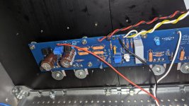
For R7' I only have a 2kR trim pot in there as that's all that the build guide said to do. Looking at the schematic I had wondered if I was meant to add in a 1k resisitor too but there doesn't seem to be space for it with the trim pot in there.
Attached a Pic of r7 trim pot if it helps
For R7' I only have a 2kR trim pot in there as that's all that the build guide said to do. Looking at the schematic I had wondered if I was meant to add in a 1k resisitor too but there doesn't seem to be space for it with the trim pot in there.
Attached a Pic of r7 trim pot if it helps
Attachments

you did well , as far as I can see
anyway - positive DC offset means lower mosfets aren't open, presenting too high impedance so output node is going up in level
with one VMeter between output and GND , observing DC offset, and second VMeter across any source resistor , for observing Iq (see prescribed value in thread) , if you vary trimpot in FE , is there any change in DC Offset at output?
how you arranged R8,R8'
from where you got input JFets?
Alright. Ill take those measurements after work today and report them back here then.
R8 I just have a 1k fixed resistor in place instead of the pot as id read a few posts in this thread saying that it is better that way.
I got the LSJ74 quad match off the diyaudio store.
Wondering if it could actually be the JFets as all I did to check them was use the diode function on my DMM to check for shorts. I didnt recheck Idss
Last edited:
Ok so I went and adjusted the offset and I dropped from 24v to 0.5v in a couple turns.
R8 is 8.44v across it
R8 is 8.44v across it
That could be okay reading... What is the voltage drop across R7?
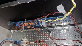
Also, I see that you used what seems like a lower wattage R18, R19 and R16, R17. Did any of these resistors go open circuit when the MOSFET's were connected to ground?
Also, I see that you used what seems like a lower wattage R18, R19 and R16, R17. Did any of these resistors go open circuit when the MOSFET's were connected to ground?
Voltage drop is 8.44v across R7. I got the channel working.
I think what I did wrong was I seen the 24v on the speaker terminals after having the mosfets shorted and assumed there was still a problem. When all I had to do was turn the R7 trim pot up more to cause enough of a voltage drop to open the mosfets and was worried about trying to turn the amp on and potentially ruin some parts.
You live and you learn though and I'm glad it's working.
Thank you very much for your guys help though.
Hopefully this new ztx450 will arrive in a few days and I can get the other channel going too
- Home
- Amplifiers
- Pass Labs
- Aleph J illustrated build guide