Best matching would be at the amplifier operating point. But that is not always possible so match as close as your tracer can get and call it a day.
You want to match Vgs for a given Iq and Vds.
Since you have an operating amplifier, you can measure those parameters.
You want to match Vgs for a given Iq and Vds.
Since you have an operating amplifier, you can measure those parameters.

best to match them at Iq prescribed for exact circuit, measuring Ugs
if only lower level of Iq for matching is possible, that's also usable, matching "tracking" is pretty good, by experience
but, take that lower level isn't extremely lower than prescribed (in circuit)
you'll find plenty of info on Articles page of FW site
in short - everything as Ben said
if only lower level of Iq for matching is possible, that's also usable, matching "tracking" is pretty good, by experience
but, take that lower level isn't extremely lower than prescribed (in circuit)
you'll find plenty of info on Articles page of FW site
in short - everything as Ben said
Thanks for the tips guys. As you pointed out ZM, correct; curve tracer gets to about 500mA and that's it. So I'm matching them at the highest point.
BTW, if you have not tried the Fairchild (now ON Semi) FQA28N15, consider as a very good alternative. They finally came back in stock at Mouser and Newark, but they are scheduled for obsolescence. I bought a couple of tubes, and had a tube of the Fairchild parts from about 2012. The datasheet says "suitable for audio amplifiers". Interesting note that I found out these are the power devices used in one of the Accuphase Class A power amps. I had the PDF brochure that was showing the internals of the amp and I did a zoom and clean up and you could see it was that part number. If I can find that I'll post it here.
BTW, if you have not tried the Fairchild (now ON Semi) FQA28N15, consider as a very good alternative. They finally came back in stock at Mouser and Newark, but they are scheduled for obsolescence. I bought a couple of tubes, and had a tube of the Fairchild parts from about 2012. The datasheet says "suitable for audio amplifiers". Interesting note that I found out these are the power devices used in one of the Accuphase Class A power amps. I had the PDF brochure that was showing the internals of the amp and I did a zoom and clean up and you could see it was that part number. If I can find that I'll post it here.
Attachments


These parts have high enough transconductance and power dissipation to consider using as singles rather than matched pairs in the Aleph J. I did something similar with the Aleph J SS boards. That worked really well. My combo was IRFP048 above and FQH44N10 below.
The FQA28N15 should work well in both positions. They like 1.5A bias.
The FQA28N15 should work well in both positions. They like 1.5A bias.
Yup,That’s Crazy!!
There was 5317 available at Mouser 3 days ago when I last checked 😳
When I checked Wednesday, there was about 1500. I don't think Newark has changed they were around 800.
Also check arrow.com, hey have 1538 pieces today, decent price.
https://www.arrow.com/en/products/fqa28n15/on-semiconductor
This is a good website to check for semis:
https://www.trustedparts.com
https://www.arrow.com/en/products/fqa28n15/on-semiconductor
This is a good website to check for semis:
https://www.trustedparts.com
So I've been using Aleph-J for a while and have had some noise in left channel that seems very periodic like maybe once every 10 minutes there is like a static sort of sound. I purchased a new audio interface that I have to RMA because it went bad and started re-testing the Aleph-J and discovered between chassis ground and XLR pins 1/2/3 I'm measuring nearly 30VAC. Any thoughts on cause of this?
Can you sketch up a wiring diagram showing your power supply interconnections, chassis ground(s) and XLR wiring to PCB? Makes it much easier to assess.
To start; are all of your grounds to a single point? Is your XLR shield to that ground point, or the bridged chassis ground? When I say "bridged", I mean is your single point ground bus connected to chassis ground using a thermistor? (about 10 ohms cold works well) you can search in this thread for part numbers.
To start; are all of your grounds to a single point? Is your XLR shield to that ground point, or the bridged chassis ground? When I say "bridged", I mean is your single point ground bus connected to chassis ground using a thermistor? (about 10 ohms cold works well) you can search in this thread for part numbers.
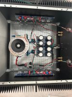
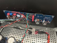
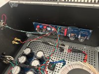
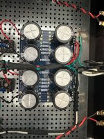
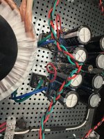
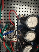
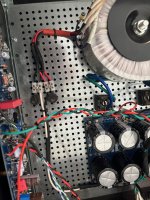
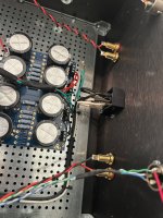
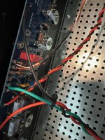
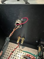
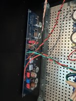
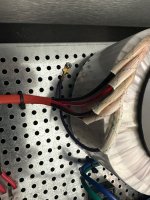
Here are pics showing the build. I built this in like 2019 so don't remember all the specifics but looks to me like things are ground directly to chassis where most convenient. Transformer ground and earth ground tie to that bottom plate with holes in it. The only other ground I see is the XLR sockets have that red jumper wire to back panel.... Of course the Aleph J boards are screwed into the heat sink but not sure if those tie to ground...
Attachments
-
 IMG_0359.jpeg599.6 KB · Views: 119
 -
 IMG_0358.jpeg415.4 KB · Views: 128
 -
 IMG_0357.jpeg458.8 KB · Views: 113
 -
 IMG_0356.jpeg487.1 KB · Views: 113
 -
 IMG_0355.jpeg562.7 KB · Views: 104
 -
 IMG_0354.jpeg521.6 KB · Views: 111
 -
 IMG_0353.jpeg537 KB · Views: 105
 -
 IMG_0351.jpeg596.2 KB · Views: 102
 -
 IMG_0350.jpeg511.5 KB · Views: 98
 -
 IMG_0349.jpeg489.6 KB · Views: 112
 -
 IMG_0348.jpeg354.3 KB · Views: 101
 -
 IMG_0347.jpeg419.8 KB · Views: 107
 -
 IMG_0352.jpeg528.6 KB · Views: 124
Last edited:
@jf4828
Maybe I can't see it well, but where is the ground from your PS board connected? How is it connected to chassis ground?
Best,
Anand.
Maybe I can't see it well, but where is the ground from your PS board connected? How is it connected to chassis ground?
Best,
Anand.
It looks like PS is grounded through ground on the amplifier board via the XLR grounds connected to the chassis. So there is no ground lift. Correction: XLR pin 1 is not connected to chassis, so PS ground is not connected to chassis, only XLR case connected to chassis.
Strange that 30VAC would appear on all pins of the XLR jack.
Intermittent noise may be caused by bad solder joints.
Suggest use a voltmeter and check that DC voltages are correct at the power supply and at the amplifier boards and re-check AC voltage at XLR jack.
Strange that 30VAC would appear on all pins of the XLR jack.
Intermittent noise may be caused by bad solder joints.
Suggest use a voltmeter and check that DC voltages are correct at the power supply and at the amplifier boards and re-check AC voltage at XLR jack.
Last edited:
first check continuity between audio GND (GND on cap bank) and case; of course while amp powered off
it's either 0R if you did directly connect GND and case/safety GND, or 10-ish ohms, if there is NTC between audio GND and case/safety GND
it's either 0R if you did directly connect GND and case/safety GND, or 10-ish ohms, if there is NTC between audio GND and case/safety GND
and discovered between chassis ground and XLR pins 1/2/3 I'm measuring nearly 30VAC.
30VAC between the chassis and all pins of both XLRs would be odd. It's even more strange to me because one of the pins (pin 1) for both XLR jacks is connected to the chassis, so...
I'd advise checking again and saying exactly where the probes are touching when you're taking your measurements and how the DMM is set. A pic of the DMM during one of the measurements is even better.
Check resistance from pin one of both XLRs to your mains earth lug on the chassis floor.
You could try adding a ground loop break between the "GND" of the PSU board and the chassis. If you have a CL-60 (or something else you're confident in using) handy, you can test it in <30s to see if it helps / changes things.
Edited to add - Why not do a quick check for the resistance between all the pins within and between the XLR jacks. May or may not confirm a suspicion.
Last edited:
- Home
- Amplifiers
- Pass Labs
- Aleph J illustrated build guide