These are the small TO-92 heatsinks that I used in my F5m:
532-575200B00
They are best installed before the parts are soldered into the board.
532-575200B00
They are best installed before the parts are soldered into the board.

Thanks for the feedback all. I've been running them with the clip on sinks, and they're right around the 36C mark. I added some high performance paste into the walls of the sink before sliding them over. I can tell you the sound is great! The bump in power has made the difference I was looking for. Previously using the Antek 18V transformer. I found the Plitrons (400VA, 22V secondary) in a shelf I had bought in 2014, and forgot about them. So after reading the threads on using a higher rail supply and asking some questions, the first amp is up and running. I also changed the chokes from a 159ZJ to a 159ZL (10mH). Excellent! I've also dropped the bias a bit from 450mV to 420mV to offset the higher rail supply. Yup, it warms up quite a bit faster. But all good so far, amp #2 coming up this week.
Yes...the legs of the devices are a little thin for that kind of pressure. I also found using a bit of good compound really helps to get them on easier and better transfer.These are the small TO-92 heatsinks that I used in my F5m:
532-575200B00
They are best installed before the parts are soldered into the board.
It would be nice to know what a realistic de-rating for temperature is. As mentioned I'm seeing about 36C to 40C, with rails at 28V, BL devices at just under 10mA. So...it's breaking some barriers here at 3V over maximum D-S volts already. And at 70% of maximum dissipation. The heat sinks must be helping. Too bad we can't know what the temperature limit is before the ca-ca hits the fan. May find out soon enough! Keeping the current at 400mV/470R might be an option to consider.
In the AJ, the jfets are not running at Idss. The total current through the jfets is controlled by the Q2 current source at about 8.4mA, so say about 4.2mA for each jfet without a signal (assuming everything is working fine and dc offset is close to zero, etc...) When you play a signal, those values vary but even with a large output they probably are still in the 3 to 5mA range.
Last edited:
Thanks Dennis, makes perfect sense now that you pointed that out. I also re-read NP's paper on the F5 Turbo where he describes running the devices at higher rails, 32V, about 4V higher than my case.
"The average dissipation of the Jfets with a 32V supply will be about 28 volts times the operating current. A 2SK170 or 2SJ74 with a 10 mA Idss will
operate at about 8 mA in this circuit, which gives a dissipation of about 220 mW. A quick calculation shows that its maximum junction temperature at 220 mW is reached with an ambient temperature of about 70 deg C. A wise DIYer will either select a Jfet with a lesser Idss (say 8 mA) and/or see to it that the Jfets gets some cool air or a little heat sink..."
So we're a long way off in my amp. as it has adequate ventilation and a fan on the top cover (runs very slow, not audible but moves just enough air) and the temperature inside will likely reach about 60C maximum, but I'll verify that in the next day or so.
I designed and built these cases before such sizes were even available. I wouldn't do it again if given a choice, too much work!
Attachments

Last edited:

I think a lot of builders dismiss using fans...should not be the case. I actually have 5. I mounted four of these perfectly square on the bottom of the heat sinks, directly below the center of each pair of power devices. F410T-12LC. You cannot see them as the width is exactly the same as the heat sink.
For the top fan I used this: Noctua NF-P12 redux-900.
I designed and built a microcontroller based solution that includes a soft start circuit and monitors a pair of LM35 heat sink mounted temperature sensors. The fans are all 12V. The small ARM controller signals a switchable 8V regulator to run the fans, and you can hear them only within a foot or so away. If you think these little fans are not effective, try them and see! Since they move air right at the heat sink channels right at the power device location they're effective. So they only get enabled when the temperature reaches 49C, and I have about 4 degrees hysteresis. The bi-color LED at the center switches from green to orange when cooling cycles making it easy to track how effective it is. The amps seem to run perfectly in this zone!

Will the increase in voltage rails provide any benefits? You'll be dissipating more heat, but will you be getting more power out of Aleph J...?
Thank you! @TungstenAudio @Ben Mah @Zen Mod
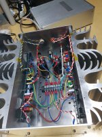
I've added extra capacitors bank (Kemet 40V 36000uf).
The Kemet 40V 36000uf has mounting stud(?) then I've cut it.
The power rail was +/- 24.2VDC before.
It is +/-22VDC now. I don't know why extra capacitors drop the power rail voltage.
The turn-off-sound seems to be 'normal'.
I've added extra capacitors bank (Kemet 40V 36000uf).
The Kemet 40V 36000uf has mounting stud(?) then I've cut it.
The power rail was +/- 24.2VDC before.
It is +/-22VDC now. I don't know why extra capacitors drop the power rail voltage.
The turn-off-sound seems to be 'normal'.
Attachments

Will the increase in voltage rails provide any benefits? You'll be dissipating more heat, but will you be getting more power out of Aleph J...?
In my system, it has to a reasonable degree. Is it subjective? Perhaps but unlikely. Overall this certainly has some dependency on the speaker load. Peak power depends on the I-V phase relationship, when they're in phase, full power is delivered. If I (and I haven't) connect the amp up to my test load cell where there's a couple of Arcol 8 ohm, 300W non-inductive load resistors and measure, power will be higher! All other things equal in system there is more energy with the preamp at the identical output on the same track. But a speaker presents a complex load that includes inductance, so it could present more power based on the signal that's being driven at that time. (voltage vs current delivery) What I'll probably end up doing is bumping the current back up to around 430mV/470R to take full advantage of the higher voltage. BTW - the Plitrons are MUCH better at the same VA rating for current delivery of the Antek! I can tell you (and as your quetion alluded to) it runs warmer at the higher rail voltage, the cooling fans cycle more and longer (depends on room temperature too) If you want to find out yourself, go the other way - reduce your rail voltage and see if it has less volume. I think the answer is clear.
One important thing I've learned about the AJ is to just listen and let the ears decide. I have a bench of equipment to perform qualitative tests - the load cell, an Agilent scope with FFT, an HP 8903B test set, and PC based software. So far I've refused to bend and connect it up because when I make changes and listen, that's the real test. You know the quote from NP: "We should no more let numbers define audio quality..." I'm a believer.
I used to live by the design numbers - total modelling on LTSpice/PCAD, make a board, bench test and tune it using all the instruments and finally listen, only to find that it wasn't so good. But all parameters of simulation and test said it should be. That's wrong! There's magic in the approach of NP's thoughtful, intellectual designs and the sound proves it! We get to take advantage of it for the cost of parts and time. What a great deal! So I tip my hat to the man that made this great sound possible - Nelson Pass.
Hope my answer to your question didn't get lost in the blither, @Extreme_Boky!
Wow, nice work. I see you're using the Auricap XO for coupling. I had these as well, and ended up switching to Clarity cap CMR from pCx. Recommended highly, what a difference.Thank you! @TungstenAudio @Ben Mah @Zen Mod
I've added extra capacitors bank (Kemet 40V 36000uf).
The Kemet 40V 36000uf has mounting stud(?) then I've cut it.
The power rail was +/- 24.2VDC before.
It is +/-22VDC now. I don't know why extra capacitors drop the power rail voltage.
The turn-off-sound seems to be 'normal'.
namghiwook,
I do not have any capacitance multiplier supplies in my amplifiers (I use CLC) but the voltage drop seems strange. I assume you have not made any changes to the power supply.
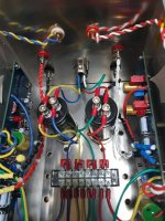
You can check to see if it is the capacitors that are causing the voltage drop by temporarily taking the capacitors out of the circuit. It looks like the yellow and green wires to and from the capacitors are the ground wires so they can stay in place. To take the capacitors out of the circuit disconnect the two red wires (V+?) from the capacitor and connect the ends together with a screw and nut, and disconnect the two blue wires (V-?) from the capacitor and connect the ends together with a screw and nut. Wrap exposed connections in electrical tape if there is a chance that they may come into contact with anything.
Assuming I identified the wires correctly the capacitors are now out of the circuit and you can power up and measure the voltage without the capacitors in place.
I do not have any capacitance multiplier supplies in my amplifiers (I use CLC) but the voltage drop seems strange. I assume you have not made any changes to the power supply.
You can check to see if it is the capacitors that are causing the voltage drop by temporarily taking the capacitors out of the circuit. It looks like the yellow and green wires to and from the capacitors are the ground wires so they can stay in place. To take the capacitors out of the circuit disconnect the two red wires (V+?) from the capacitor and connect the ends together with a screw and nut, and disconnect the two blue wires (V-?) from the capacitor and connect the ends together with a screw and nut. Wrap exposed connections in electrical tape if there is a chance that they may come into contact with anything.
Assuming I identified the wires correctly the capacitors are now out of the circuit and you can power up and measure the voltage without the capacitors in place.
@Ben Mah
Yes, You are right.
I did it as you guided, no difference!
The rail voltage is +/-21.8 VDC.
'+/-24.2' rail voltage came from mal function before.
BTW.. +/-26.8VDC PSU voltage with no load then the sag drop (5VDC) seems to be so huge.
Yes, You are right.
I did it as you guided, no difference!
The rail voltage is +/-21.8 VDC.
'+/-24.2' rail voltage came from mal function before.
BTW.. +/-26.8VDC PSU voltage with no load then the sag drop (5VDC) seems to be so huge.
Hi all,
I have one NFET (Q7) misbehaving, it's running about 10C hotter than the others. Ditto for it's 0.47R resistor that's a bit warmer. I didn't leave it on long enough to see how it it gets. Bias current looks normal around 430mV/470R (28V rails) So...if replacement is needed could Q7 be replaced so long as it curve matches Q8? Or better for all 4?
I have one NFET (Q7) misbehaving, it's running about 10C hotter than the others. Ditto for it's 0.47R resistor that's a bit warmer. I didn't leave it on long enough to see how it it gets. Bias current looks normal around 430mV/470R (28V rails) So...if replacement is needed could Q7 be replaced so long as it curve matches Q8? Or better for all 4?
No need to change all four. It suffices to find a part that matches better to either Q7 or Q8.
In the experience of those here, how much mismatch of the output FETs is tolerable before it becomes audible? My tracer shows curves to a maximum of 500mA drain current. If looking at the curve where should the match be primarily considered...at what voltage? Since gate threshold is in the 2 to 4 volt range, is this where it's important?
- Home
- Amplifiers
- Pass Labs
- Aleph J illustrated build guide