What are the key parts for Aleph J that are worth upgrading beyond the standard BOM?
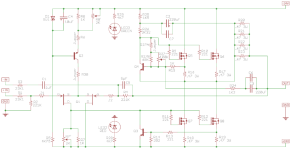
Concentrate on R1, R2, R3, R4 and R24 and associated caps in the direct signal path?
I’m thinking of using s/z-foils - to try and inject some additional openness and move even more towards the speed/fire of tube amps if that is a plausible aim.
Concentrate on R1, R2, R3, R4 and R24 and associated caps in the direct signal path?
I’m thinking of using s/z-foils - to try and inject some additional openness and move even more towards the speed/fire of tube amps if that is a plausible aim.
Dale resistors are cheap and sound good, but my tinkering heart says you could always try fancy components... whether it sounds superior will require some A-B comparisons. Not so easy with soldered components like resistors. You should also consider replacing R9, R10, R11, and R12.
I always advocate upgrading signal Caps. Film caps, where feasible, with copper film bypasses are my go to.
I always advocate upgrading signal Caps. Film caps, where feasible, with copper film bypasses are my go to.
Thanks @Vshredder - do you know what the purpose of R9 to R12 is in the circuit?
For non-critical I will use either Vishay REY or Dale RN65.
For non-critical I will use either Vishay REY or Dale RN65.
Well, from what I can tell, R11 and R12 are the main signal path to the output stage from the input stage and R9 and R10 are on the signal path for Negative Feedback. But I could be wrong about the later.
ZM, after researching a bit, I understand the difficulty of explaining issues with my previous idea... Too many things wrong with the whole idea. So following previous solutions and Papa Pass's Sage advice... I inverted the whole thing with the intent of using IRFP9240 outputs. One thing I was confused on is whether inverting C2 and C3 polarity is correct (Not an issue with film caps, but I want it to look correct).

Gate-stoppers to prevent possible mosfet oscillation.Thanks @Vshredder - do you know what the purpose of R9 to R12 is in the circuit?
For non-critical I will use either Vishay REY or Dale RN65.
Foil resistors may not bring a better sound.
There was theoretical explanation somewhere where on this forum.
Thanks I think I found a few tips on that - traditional resistors may we’ll be better suited. I’ll stick with using a combination of Takman REY and Dales.Foil resistors may not bring a better sound.
There was theoretical explanation somewhere where on this forum.
I noticed the symbol for the IRFP9240 was messed up, so I fixed that, and I removed the polarity for the negative feedback path after reading that some people use bipolar caps there with no issues.I inverted the whole thing with the intent of using IRFP9240 outputs. One thing I was confused on is whether inverting C2 and C3 polarity is correct (Not an issue with film caps, but I want it to look correct).
Attachments
ZM, after researching a bit,
open dedicated thread for your idea and we will help
I noticed
you didn't ........ enough
anyhow, that horse beaten to death, already ...... luckilly just figure of speach
see here, read, search for few more threads with same idea, think
https://www.diyaudio.com/community/threads/inverted-aleph-j.243204/
Would probably end up similar to the one you mentioned. I will play around in Spice and see if I can figure it out, I'll make that thread if it doesn't work out. Thanks again.open dedicated thread for your idea and we will help
And for more critical?Thanks @Vshredder - do you know what the purpose of R9 to R12 is in the circuit?
For non-critical I will use either Vishay REY or Dale RN65.
Hello everyone! I've been struggling with one channel on my Aleph J build.
I must have messed something up in the initial testing, and now I can only get 7.85v at R8 and 0v at R18.
I did manage to toast a few of the 0.47 resistors by turning the potentiometers, but I changed them all out and also got a new jfet+mosfet kit from the diyaudiostore, just in case they got burned too. Desoldered and measured components again, reset the potentiometers. Still 7.85v at R8.
I can't figure out what's wrong. Any suggestions? Thanks!
As usual:
1) Post the schematic you are using for your Aleph J build.
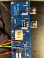
2) Upload clear pictures of your board as mounted on the heatsink (the channel that is not working).
Make sure you have a tested and working power supply, i.e. your voltage rails should be around +/- 22 to +/- 28V.
Thanks!
Best,
Anand.
1) Post the schematic you are using for your Aleph J build.
2) Upload clear pictures of your board as mounted on the heatsink (the channel that is not working).
Make sure you have a tested and working power supply, i.e. your voltage rails should be around +/- 22 to +/- 28V.
Thanks!
Best,
Anand.
Thank you for your quick reply, Anand!
I have a working power supply, thankfully. I used the schematic from the first post in this thread and followed this build guide: https://diyalephj.blogspot.com/
My boards look a mess from all the desoldering and resoldering, but here they are.
I have a working power supply, thankfully. I used the schematic from the first post in this thread and followed this build guide: https://diyalephj.blogspot.com/
My boards look a mess from all the desoldering and resoldering, but here they are.
Attachments
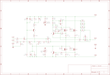
Check the attached; I removed the jumpers and R7 & R8' from the schematics to avoid confusion .... Read the instructions in the bottom right corner. Post the measured voltages.
If R18 reads zero, you don't have 4V across R7 (and/or the Q5 is not conducting)
- make sure your R7 trim pot is working correctly and soldered properly; and that it makes contact with the PCB. Check and confirm that R8 is 1K and that it makes contact with the PCB
- If R18 is still zero, the JFETs are most likely bad because there's no current through R8, so replace the JFETs.
- confirm Q2 is the correct part, soldered the correct way
But... the bottom line is:
The best way to go about this problem is to take the measurements first, as per my instructions in the jpg I attached.... before you start replacing the expensive JFETs/MOSFETs. Post the results here and we'll have a look.
Which are the most influential resistors in Aleph J - I'm thinking of upgrading R1,R2,R3, R4 & R27 to AN niobium and stick to the BOM or Takman REY everywhere else. Opinions?
After R1,R2,R3, R4 & R27, the most important seem to be: R9-R12 at the output stage, with R16-19 before/after the mosfet.
R16-19 are 3W resistors, by what I can see most ‘audiophile’ resistors including AudioNote only go upto 2w and I don’t want to consider multiple resistors. Mundorf M-Resist Ultra MREU30 30W Film Resistors are available in .47R and they are rated to 3W in free air. Worth considering?
R16-19 are 3W resistors, by what I can see most ‘audiophile’ resistors including AudioNote only go upto 2w and I don’t want to consider multiple resistors. Mundorf M-Resist Ultra MREU30 30W Film Resistors are available in .47R and they are rated to 3W in free air. Worth considering?
- Home
- Amplifiers
- Pass Labs
- Aleph J illustrated build guide


