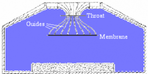
It kind of looks like a Beveridge lens without the guides:
technical_details
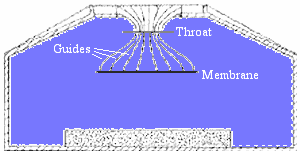
I share some concerns with fluid about this proposal. Basically we are creating a front chamber and have sort of a diffraction slot. The Beveridge lens shows guides and used a flat source, not cones like we do.
The Beyma TPL 150 would be sort of like a short array shape (long in vertical direction, short in horizontal) and have some vertical directivity to work with. But it won't be easy to hand off from that to the arrayed drivers. If I were to try or pick a tweeter it would be either something like that Beyma (rectangular shaped) or a short array of small tweeters.
technical_details
I share some concerns with fluid about this proposal. Basically we are creating a front chamber and have sort of a diffraction slot. The Beveridge lens shows guides and used a flat source, not cones like we do.
The Beyma TPL 150 would be sort of like a short array shape (long in vertical direction, short in horizontal) and have some vertical directivity to work with. But it won't be easy to hand off from that to the arrayed drivers. If I were to try or pick a tweeter it would be either something like that Beyma (rectangular shaped) or a short array of small tweeters.
Attachments
Last edited:
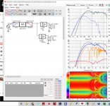
Digging into Vituix and try to implement the Beyma 150 as central tweeter flanked by 13 Vifa:s on either side:

(how can I make the pictures showing in correct size? When using the Attachment feature the just show up as thumbnails..?)
Looks like it could be made to work. Pretty big inductors...😉
Ordered a few different absorbtion sheets for evaluation. Hopefullt some measurements could be done this weekend.
(how can I make the pictures showing in correct size? When using the Attachment feature the just show up as thumbnails..?)
Looks like it could be made to work. Pretty big inductors...😉
Ordered a few different absorbtion sheets for evaluation. Hopefullt some measurements could be done this weekend.
That's looking quite nicely.
What does the horizontal wavefront look like? Curious to find out what the jump in directivity above 10K means.
You can save the group of images from within Vituixcad. Its right there under the right mouse button as: Export six-pack.
Same goes for the schematics. I usually copy the link of the image I attach to a post and put that between the IMG tags in the post itself.
Your picture displays in full size when clicked upon. Including a picture that big would not work well within a post.
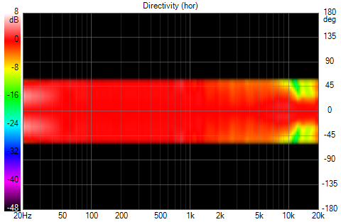
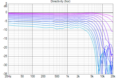
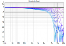
There is a narrowing of the horizontal directivity above 10K which explains the jump:
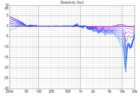
The vertical directivity looks like this (5 degree increments):
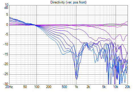
I was working with adjusting the inductances to have as an uniform response as possible within a +/-10 degree vertical window (which should cover both seated and standing) and at the same time keep it narrow for avoiding ceiling and floor reflections. Lots can be done here by adjusting the phase relationship between the drivers!
The vertical directivity looks like this (5 degree increments):
I was working with adjusting the inductances to have as an uniform response as possible within a +/-10 degree vertical window (which should cover both seated and standing) and at the same time keep it narrow for avoiding ceiling and floor reflections. Lots can be done here by adjusting the phase relationship between the drivers!
Attachments


From these measurements it looks like the TPL150 drops off a cliff beyond 15 degrees off axisCurious to find out what the jump in directivity above 10K means.
Attachments
I see 😱
It could still work if the side reflections below 10K are somewhat absorbed. That would make for a very clean listening window I suppose...
It could still work if the side reflections below 10K are somewhat absorbed. That would make for a very clean listening window I suppose...
One thing that keeps bugging me is how low the contribution is of the outer driver groups to the total power. getting them to work a bit harder would help the most important drivers as they carry the load so to speak. It would also help to even out a lot more of the room effects. However the top end is cleaner than my (still full range) solution.
You've somewhat created an expanding array, but as said, getting the outer driver groups to work a little harder would probably benefit the entire array of drivers. The fractal array posted in the multi way forum might be good for inspiration.
You've somewhat created an expanding array, but as said, getting the outer driver groups to work a little harder would probably benefit the entire array of drivers. The fractal array posted in the multi way forum might be good for inspiration.
Last edited:
Hi Crumbo:
I have to say I'm very impressed with your results. You went beyond my meager efforts in Vituix sims but being able to get this response with a quality device like TPL200 is compelling. Something I obviously didn't think possible else I very likely would have tried it when I was playing with the concept
I would second Wesayso's comments regarding early reflections. Given how wide your horizontal response is you most certainly need absorption. It would almost be worth it to narrow it electro-acoustically except that can't be done without additonal columns of drivers. It would be so nice to be able to stand one of these arrays just a small distance out into the room and use beam steering instead of absorption panels to eliminate early reflections. With TC9FD one can actually afford those additional drivers.
And again on greater contributions from the outer drivers. IIRC yours are weighted fairly low. With DSP instead of passive filtering, you could unshade them at the low end. This may not matter if you don't listen at high volumes or if you offload to subs. I would check THD at listening level.
Have you done Vituix sims using the driver offset feature to see the response at seated ear height? That is a view worth looking at!
Hi!
Yes, I would definitely like to spread out the load on the Vifas in the low range better. I'll try some different wiring of the drivers and see what could be done, still keeping a reasonable impedance. Using DSP would be another option, but that would require even more channels/amps.
nc535: LOL, I was just thinking of some kind of beam steering by using a second column in order to get a narrower response. Actually, I have 70 drivers to play with (although a few will be used in the Haas-kickers). Made a quick test in Vituix yesterday but couldn’t get it to work by using a FIR filter to gradually turn the phase difference for keeping the lobe steady. It seemed to work in maybe the top 2 octaves only, then the horizontal distance between the drivers was too small (about 85 mm c-c) for making any off-axis “nulls”. Do you (or somebody else) have another idea of how to accomplish this?
Thanks wesayso, I’ll check out that fractal array link!
Have you done Vituix sims using the driver offset feature to see the response at seated ear height? That is a view worth looking at!
No, not yet. So far I have looked on the vertical dispersion plot and it seems to be ok in a +10/-5 degree window. Ear height while seated would be about 1 m (which is the design axis). The tweeter is placed at the middle point between floor and ceiling, which is 1241,5 mm above the floor.
In my sims, I had a lot of trouble maintaining flat response that far off center. This led me to placing the tweeter at ear height rather than array center. OTOH, I was optimizing for smoothness rather than averaging over a vertical window.
As to beam steering, what I found most effective in keeping sound off the sidewalls in simulation was modeling the Vifas as dipoles. The in-simulation caveat is caution about the potential effect of nearby sidewalls on the dipole effect.
As to beam steering, what I found most effective in keeping sound off the sidewalls in simulation was modeling the Vifas as dipoles. The in-simulation caveat is caution about the potential effect of nearby sidewalls on the dipole effect.
In my sims, I had a lot of trouble maintaining flat response that far off center. This led me to placing the tweeter at ear height rather than array center. OTOH, I was optimizing for smoothness rather than averaging over a vertical window.
As to beam steering, what I found most effective in keeping sound off the sidewalls in simulation was modeling the Vifas as dipoles. The in-simulation caveat is caution about the potential effect of nearby sidewalls on the dipole effect.
Can you model dipoles in Vituixcad? It would sure be interesting to have a look into it.
Found the diffraction feature in vituix and made a quick simulation of a single driver in a 10 cm wide baffle.
Horizontals in closed box (5 degree increments up to 60 degrees off axis):

Same with open baffle:
There is for sure some potential there. As I still need to have the speakers close to the corners I would probably need lots of absorption behind the open baffles to absorb the backward wave... Hope to get some time to do measurements soon!
Horizontals in closed box (5 degree increments up to 60 degrees off axis):
Same with open baffle:
There is for sure some potential there. As I still need to have the speakers close to the corners I would probably need lots of absorption behind the open baffles to absorb the backward wave... Hope to get some time to do measurements soon!
Attachments

Can you model dipoles in Vituixcad? It would sure be interesting to have a look into it.
Here is a dipole example. Two coincident drivers, one fed delayed and out of phase to simulate the backwave. If you search Vituix forum for Kimmostos reply to my post re' dipole, you will find where he told me how to do it.
Nice driver, too bad you can't buy it. Point the tool at a real driver clicking in the file icon next to half space response in the lower right corner...Found the diffraction feature in vituix and made a quick simulation of a single driver in a 10 cm wide baffle.
Horizontals in closed box (5 degree increments up to 60 degrees off axis):
Same with open baffle:
There is for sure some potential there. As I still need to have the speakers close to the corners I would probably need lots of absorption behind the open baffles to absorb the backward wave... Hope to get some time to do measurements soon!
Use SPL Trace tool on data sheet if you don't have a measurement.
If you absorb the back wave successfully you won't a get dipole response 😉As I still need to have the speakers close to the corners I would probably need lots of absorption behind the open baffles to absorb the backward wave... Hope to get some time to do measurements soon!
The effect will be based on the path length difference and the strength of the rear wave, the description was a lot of absorption and a short distance.
The effect will be based on the path length difference and the strength of the rear wave, the description was a lot of absorption and a short distance.
I wasn't thinking THAT short distance. There should be room for the back wave to develop and travel around the baffle, but the reflection in the back wall should be absorbed or it will create lots of interference with the front wave.
However, I think a nice smooth response will be really difficult to accomplish in my listening room using dipole arrays. There is also the huge loss of efficiency in the low range to deal with when going dipole. I’m not ruling it out completely just yet, but I think that using absorption to narrow the horizontal directivity would be the way to go here.
- Home
- Loudspeakers
- Full Range
- Another corner line array, 28 TC9FD18