And where do I get that number? Is something easily found?
Or you are meaning the Grado model, which is which I don't know at the moment.
The metal cylinder it came on is somewhere here at home, which hopefully I fill find next week.
It's a pity nothing is written on the cartridge, except JG.
Or you are meaning the Grado model, which is which I don't know at the moment.
The metal cylinder it came on is somewhere here at home, which hopefully I fill find next week.
It's a pity nothing is written on the cartridge, except JG.
Opa1641 single channel $1.68 😀
Excellent suggestion, Hans, and great price. Thanks!
Along with the dual OPA1652, two excellent FET opamps for any of these RIAA projects. Should be quite compact with the dual.
Now I will compare THD and noise.
What are the best frequencies to try for THD?
The last time I measured RIAA amplifier distortion, I did it at 100 Hz, 1 kHz and 10 kHz, but that is rather arbitrary.
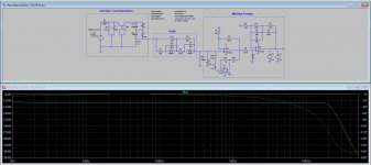
Let's hope I simulated it right this time.
The curve is 1dB higher below 5Hz, but who cares about that.
The rest is how is should be?
Looks perfect to me !
Hans
Do you still want to use your stock of old OPA627's and OPA637's?
Sorry to delay in answering this question of yours.
This week I will start looking at the boxes I have with opamps from the times manufacturers sent samples for free. I believe there are some OPAs there.
My idea is to try to build a preamp using some of the proto-boards I have, or if necessary to adapt an existing one that is easy modifiable.
Then, with time, I will design my own pcb. My concern is more if I have the passive parts I'd need, particularly the caps.
The problem is that it would take at least two months to get the right parts to build one of the ones you helped design. So I may buy the parts, but not keep waiting for they to come.
Don't you think that should cover all the options?
These times we are going through demand I get to build a high quality preamp right away, and start capturing the LPs. That would get me an exciting job to do, capturing and processing the files. Don't you think it might be a good way to put your brain to work?
Just to make things clear: the preamp I'm most interested in building is the one you helped me with.
The other I mention is something to build until I get to get the parts. Things though might get interesting if I do find the OPA627 or 637 I think I got to get. Those would be superb opamps which would turn out into a superb preamp.
The other I mention is something to build until I get to get the parts. Things though might get interesting if I do find the OPA627 or 637 I think I got to get. Those would be superb opamps which would turn out into a superb preamp.
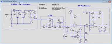
I made a slight change in the layout by replacing the 2n5 cap over the first stage to behind R10, now being 6nF.
This has several advantages:
1) you can freely change the gain of the first amp without worrying about changing the parallel cap.
2) when using the "cooled" version, the 207pF cap par to the 57K4 resistor can be discarded, making it a much easier to find the right resistance value when changing to another Cart.
I rounded the S/N figures to integers, but in fact there is only 0.5dB between the hot version and the cooled version.
I have no TL071 model but with 18nV/rtHz @ 1Khz I think the LT1792 with 4.2nV/rtHz is almost as good as it can be.
The OPA164x could be an alternative with single, dual and quadruple versions.
And regarding a S/N of 73dB-A, keep in mind that some of the most expensive and well regarded Riaa preamps (Stereophile) have lower noise figures, such as the $60,000,- Vitus with 62.8dB-A and the $36.000,- Boulder 2008 with even 58dB-A.
As a reference see here the noise from a 75dB-A preamp L/R in the lower trace against the surface noise of a new Feickert test LP with resp. an unmodulated track versus a track with a 1Khz test tone at 5cm/sec.
Where they are closest, there is still more than 15dB between the surface noise and the preamp noise, showing that even 66dB-A will only increase the surface noise by an almost insignificant 1dB.
The Boulder 208, producing comparable noise as the surface noise, will increase noise by 3dB, under the assumption that Stereophile measured correctly.
Maybe adding the noise was part of the magic of the Boulder, who knows.
Hans
Hans, I own a Shure V15 type III, could I use opa16412 with the same components as your schematic? What's the output impedance?
Dual
OPA1642AID | Amplificador operacional OPA1642AID Audio, 4,5 → 36 V 11MHZ SOIC, 8 pines 100 Hz | RS Components
Four channels
https://es.farnell.com/texas-instruments/opa1644aid/ic-op-amp-jfet-11mhz-14soic/dp/1823862?st=opa1644
Last edited:
Yes of course, the opa1642 is an excellent choice.
I’m not shure what you mean with output impedance ?
Hans
I’m not shure what you mean with output impedance ?
Hans
Just to mention it, I tried to bring Erno Borbely to this thread, to invite him.
But I was told he is no longer interested in audio matters. It's a pity.
But I was told he is no longer interested in audio matters. It's a pity.
Yes of course, the opa1642 is an excellent choice.
I’m not shure what you mean with output impedance ?
Hans
Output impedance - Wikipedia
Thanks
Felipe
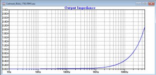
Yes I know what Impedance is, but I don't understand the reason of your question.
This amp is supposed to drive a high input impedance preamp as from the second LT1792 stage, so output impedance can never be an issue.
You could still insert an additional 100R resistor at the output to match the interconnect's impedance.
But anyhow, here is the output impedance for this Riaa preamp using the LT1792.
Hans
Attachments
Using these low offset opamps on these designs, is it possible to avoid output capacitors?
Good point.
Assuming an offset voltage of 3mV max, this translates into 300mV max at the output, so when your preamp following this Riaa preamp is DC coupled, you will need an output cap.
When also implementing the cooling, you could discard the 4.7uF because less than 0.5uA will flow into the Cart, which IMO is acceptable.
But with two additional resistors and one cap, you can even reduce this to >100nA through the Cart.
My feeling is always that the best cap is no cap, so better to leave this 4.7uF.
Hans
Attachments
Last edited:
Right, but that would give 1dB rise at 10Hz.
Not a drama, but this is where you don't want to amplify the rumble.
But as shown, the whole cap can be discarded.
Hans
Not a drama, but this is where you don't want to amplify the rumble.
But as shown, the whole cap can be discarded.
Hans
- Home
- Source & Line
- Analogue Source
- RIAA preamps versus real loads