
Yeah.... Koifarm did a great job with this construction/schematic.
Nice to hear, that you got the hum "tamed" 🙂
It is all the small improvements, that lowers the hum/noise bit by bit. Keep looking, and you´ll probably end up with less than 0.5mV 🙂
Today i did some measurements with a reverse RIAA circuit(+/-0.1db).
I like the results.
Koifarm,
Have you detailed somewhere in the thread what measurement software package you're using? Is it expensive? I like the user interface as seen on the screen shots you've provided. I currently use the free ARTA software with a good PC sound card, but don't much like ARTA's user interface. Thanks.
I have measured with rtx and MIPro and the accuracy I get is within +-.0.25dB 20-20kHz. Very low distortion, HUUUUUGE overload margin, you will burn the cartridge coils before you come close to overload this. It measures good. It sounds good. It is quiet as Koifarm described. Thanks for an excellent DIY project Mr Koifarm and BoydK.
Thanks Jazid.... Always nice to get good/great feedback.
I take no credit for the Mini-Me, just got the PCB´s made, so others could enjoy it too 🙂
I take no credit for the Mini-Me, just got the PCB´s made, so others could enjoy it too 🙂
Koifarm,
Have you detailed somewhere in the thread what measurement software package you're using? Is it expensive? I like the user interface as seen on the screen shots you've provided. I currently use the free ARTA software with a good PC sound card, but don't much like ARTA's user interface. Thanks.
Ronny is using a Velleman PCSGU250 USB Scope +Signal generator. The software comes with the unit PC-Lab 2000. Very useful little unit which I also bought for my hobby.
Last edited:
Ronny is using a Velleman PCSGU250 USB Scope +Signal generator. The software comes with the unit PC-Lab 2000. Very useful little unit which I also bought for my hobby.
Thanks. 🙂
Had 3 weeks vacation. That is why i late respond. I used velleman pcsgu250 and also digital pocketscope dso nano.
Hello
I am very interested in building this phono.
Do anyone here knows reliable seller for 6N16B tubes ?
Thanks, Krca
I am very interested in building this phono.
Do anyone here knows reliable seller for 6N16B tubes ?
Thanks, Krca
Thank You very much.
I have found the picture, looked again closely and found him.
Anyway thanks for answering & confirming.
Regards, Krca
🙂
I have found the picture, looked again closely and found him.
Anyway thanks for answering & confirming.
Regards, Krca
🙂
Hello!
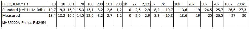
I assembled this scheme and got the following result by RIAA.
Spreadsheet/Table
I was comparing the sound with the EAR 834 and Leben rs-28cx.
I was very pleased with the results.
But there is one problem!
With a short-circuited input there is a pulsating signal from 1 to 30 mV on the output.
I think that this is because of assembly, since I was assembling several prototyping boards in different combinations.
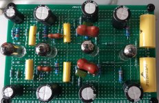
Photo
Clamping resistors didn't make any effect.
I concluded that it is necessary to make an assembly on a printed circuit board.
I'm asking for help with the purchasing of the GERBER file for this scheme.
Sorry for my English.
Best regards, Leonid.
I assembled this scheme and got the following result by RIAA.
Spreadsheet/Table
I was comparing the sound with the EAR 834 and Leben rs-28cx.
I was very pleased with the results.
But there is one problem!
With a short-circuited input there is a pulsating signal from 1 to 30 mV on the output.
I think that this is because of assembly, since I was assembling several prototyping boards in different combinations.
Photo
Clamping resistors didn't make any effect.
I concluded that it is necessary to make an assembly on a printed circuit board.
I'm asking for help with the purchasing of the GERBER file for this scheme.
Sorry for my English.
Best regards, Leonid.
Attachments
Hello
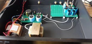
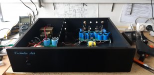
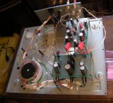
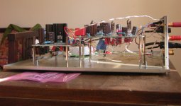
This is my first build, "junkyard" style, done for educational purposes mainly.
Before making it on the proper pcb ( thanks Flancfluster ! ) i have a question :
Generally speaking and without measuring equipment, the sound is very nice but the bass is very thinn.
My guess is that fr range below 300Hz has something like negative tilt.
So how to proceed and resolve the issue ?
Krca
Attachments
Normally there must be enough bass.
Did you use the right load for your cartridge?
What is the inputimpedance of your next stage?
How big is the output capacitor?
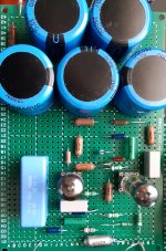
And did you use 100nf couplingcaps between the stages, i can not see the values on your pictures.
They look only 10nf. Then there is also no bass.
And measure heater voltage on the tube.
Did you use the right load for your cartridge?
What is the inputimpedance of your next stage?
How big is the output capacitor?
And did you use 100nf couplingcaps between the stages, i can not see the values on your pictures.
They look only 10nf. Then there is also no bass.
And measure heater voltage on the tube.
Last edited:
Hi!
Unfortunately, not quite, only up to 5mV
The next option I will make in different cases power supply and the actual corrector
I really like the sound
Many thanks to the author of the scheme and to all participants.
Did you use star ground to cartridge cable?i can not see it on your photo.
Shure V15/3 on Lenco L75 in stock form ( cca. 230pF ? ) + 47pF at the input connectors - not on pictures.
All elements as per schematic - 100nF coupling caps, 2u2 output coupling cap, 200pF in first RIAA filter ( parallel ), 8n2 in second RIAA filter ( parallel ), 316K precision measured resistors.
Heaters on 12,26VDC
Will check the values, they should be 100n.
Everything star grounded and from there goes one wire with 10R NTC to Earth.
Thanks for the reply.
Last edited:
So far all good.
What is the impedance of the input from the amp where the phono preamp is connected to?
You can check R2, R9 and R19 if value is to low then there is less bas.
What is the impedance of the input from the amp where the phono preamp is connected to?
You can check R2, R9 and R19 if value is to low then there is less bas.
Last edited:
Sorry for budding in between Q´s and A´s........
But a Q to Koifarm/Flancfuster.....
I see in the thread some people are wanting the gerbers for the MiniMe pcb´s. Since I´m not really up for another GB (and it´s actually your property).... would any of you mind, if I made the gerbers publicly available in this thread??
But a Q to Koifarm/Flancfuster.....
I see in the thread some people are wanting the gerbers for the MiniMe pcb´s. Since I´m not really up for another GB (and it´s actually your property).... would any of you mind, if I made the gerbers publicly available in this thread??
- Home
- Source & Line
- Analogue Source
- Mini-Me phono preamp