Depends on the forum, on Nederlands Forum over Oude Radio's threads are almost immediately closed when they move off topic - which is a nuisance sometimes.
I already reported my own topics asking for splitting...nobody looked interested yet.Maybe i should've better asked for this topic to be closed.
Did anybody say anything about PSRR affecting the output?
Whatever way you slice it and dice it, as drawn it will not work. This is simply a long tail pair with a current mirror as load, biased at about 0.5mA. Now look at the drop on R3 and R2, it’s about 15V and therefore Q2 is wrongly biased (base is at ground, collector is positive, in fact Q2 saturates). Everything else crumbles.
A typical situation when a simulator is the wrong tool if one doesn’t know what he’s doing.
Last edited:
I already reported my own topics asking for splitting...nobody looked interested yet.Maybe i should've better asked for this topic to be closed.
Do we really need more phono threads?
Probably not...if you follow the posts down to first carlmart switch you find that i abandoned this topic myself before that.So i said that his posts should be moved into Billhurv's topic on mechanical resonance as it's mostly Hans responding there.
Except people already built and used Taylor's phono preamp a long time ago...before any LtSpice ever existed.Did anybody say anything about PSRR affecting the output?
Whatever way you slice it and dice it, as drawn it will not work. This is simply a long tail pair with a current mirror as load, biased at about 0.5mA. Now look at the drop on R3 and R2, it’s about 15V and therefore Q2 is wrongly biased (base is at ground, collector is positive, in fact Q2 saturates). Everything else crumbles.
A typical situation when a simulator is the wrong tool if one doesn’t know what he’s doing.
Long tail current is 0.2mA not 0.5mA, my bad. That would work.
Except you “forgot” to short the Q2 base to the ground (in this input configuration) and avoid a wealth of noise at the output.
Except you “forgot” to short the Q2 base to the ground (in this input configuration) and avoid a wealth of noise at the output.
it was shorted to ground in the original schematic.I just added r7 there to make some checks at some point.I don't have acces at the original schematic for the moment.
There are not enough voices saying a new thread should be open to add cartridge influences on the phono stages, being them BJT or FET.
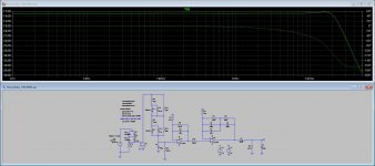
What I did was take latest Hans version to the circuit I had proposed based on Erno Borbely's proposal, and simulate it. Hopefully the variables I loaded are correct.
FET vs BJT input phono preamp
I think I converted it correctly into a working simulation and got similar results to that he got. Please do judge, particularly you Hans, if my job was correct.
.asc file is also enclosed, so anyone can check the simulation and correct what you think should be corrected.
I would appreciate if someone could redesign this schematic into the actual circuit to be used.
The input load, resistor and cap to start with, it was not what people have found out to be using test records and scopes. I wonder what other instruments could be used to check on those values.
Attachments
There's no voice saying that your posts are having anything to do with the Topic's name either...
Why don't you move into Billshuv topic ?
mechanical resonance in MMs
From now on i'm reporting every single post you put here!
Is that ok for you?
Why don't you move into Billshuv topic ?
mechanical resonance in MMs
From now on i'm reporting every single post you put here!
Is that ok for you?
What you did was exactly right for the damped version.
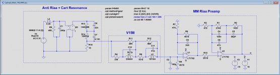
I rearanged the parts a bit, by replacing the mechanical cart resonance emulator into the generator, giving a better visibility of what is the Cart and what is the actual Riaa Preamp.
Hans
I rearanged the parts a bit, by replacing the mechanical cart resonance emulator into the generator, giving a better visibility of what is the Cart and what is the actual Riaa Preamp.
Hans
Attachments
Help, there is a Phono Police Force out there. 😀There's no voice saying that your posts are having anything to do with the Topic's name either...
Why don't you move into Billshuv topic ?
mechanical resonance in MMs
From now on i'm reporting every single post you put here!
Is that ok for you?
Hans
this post belongs here:What you did was exactly right for the damped version.
I rearanged the parts a bit, by replacing the mechanical cart resonance emulator into the generator, giving a better visibility of what is the Cart and what is the actual Riaa Preamp.
Hans
mechanical resonance in MMs
You'll get this message every single time you post here mechanical cart simulations.
Do you feel frustrated because MarcelvdG has shawn multiple time that you didn't make the right calculations on noise and try populating every single phono preamp topics with your expertise ?
Do you want me quoting every single post of yours in every phono topic you activate and be answered offtopic ?
I can be that insolent too!
Or you think that a stupid guy like me can't do it...do you?
Last edited:
What if I place a second version of Carlmarts circuit diagram with BJT input, are whe then on track again ?
Hans
P.s. in case you didn’t notice, carlmart’s circuit has absolutely nothing to do with mechanical resonance in MM’s, just for the record.
Hans
P.s. in case you didn’t notice, carlmart’s circuit has absolutely nothing to do with mechanical resonance in MM’s, just for the record.
Last edited:
That's much better 🙂 !
P.S. answer to your P.S.
even that doesn't have anything to do with this topic's name ...
P.S. answer to your P.S.
even that doesn't have anything to do with this topic's name ...
Last edited:
From now on i'm reporting every single post you put here!
Is that ok for you?
Sorry, dreamth, I do not wish to argue with you, but your claim is out of line.
What will you report me for?
There's no voice saying the opposite either, that what I'm write does not belong here.
As Hans said: you are not the police here. I haven't seen any moderators claiming something is wrong, because nothing is.
Apparently your questions were all answered, and the topic evolved. You just do not seem to accept it.
I wonder why You chose this topic to put your seeds into it...
Is there any need for a topic to evolve into something different than the Topic's name is all about?
Do you have anything to say about why a bjt input preamp would be better or worse than a FET preamp?
Is there any need for a topic to evolve into something different than the Topic's name is all about?
Do you have anything to say about why a bjt input preamp would be better or worse than a FET preamp?
- Status
- Not open for further replies.
- Home
- Source & Line
- Analogue Source
- FET vs BJT input phono preamp