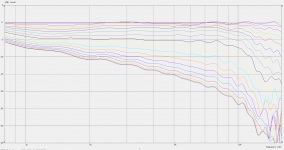
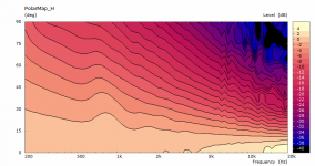
Here's my measurements of my 15" x 11" x 114mm deep guide measured in the warehouse.
HF10AK + 12P80ND + custom WG
Three EQs were required to create the +/-3dB flatness for testing.
I've booked a day in a "5 Mtr Calibrated Anechoic Test Room" - next Thursday. The owner designs and manufactures air horns for trains. Interesting!
HF10AK + 12P80ND + custom WG
Three EQs were required to create the +/-3dB flatness for testing.
I've booked a day in a "5 Mtr Calibrated Anechoic Test Room" - next Thursday. The owner designs and manufactures air horns for trains. Interesting!
Last edited:
You are only one single step from turning the measurements you took into anechoic. You need to apply a time window to the impulse response(s). If I read the graphs right, you have more than 6 ms of reflection-free time, which is good. I don't use REW so I can't help you with that.
Very interesting to see how the results in the test room compare. ~how much did the booking cost? (assuming your OK with disclosing that)
*Yeah time gating your REW results is very easy and gets rid of reflections at the expense of imposing a low frequency limit and reducing frequency resolution.
*Yeah time gating your REW results is very easy and gets rid of reflections at the expense of imposing a low frequency limit and reducing frequency resolution.
Those 6 ms will probably cover most of the impulse response of the waveguide+driver alone so applying the time window will not reduce any information content, i.e. there's no reduction of "resolution" to worry about.
Sorry, what?
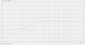
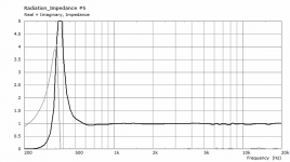
Well, it looks like that the horn has a linear impedance only from approx 3,5 kHz and up. No?
//
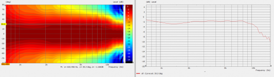
This is the latest for the 1.4" HF146 guide.
15"x 11" x 114mm.
Bit wibbly up top at the moment using these settings.
15"x 11" x 114mm.
Bit wibbly up top at the moment using these settings.
Code:
Mesh.AngularSegments = 120
Mesh.LengthSegments = 20
Mesh.CornerSegments = 6
Mesh.ThroatSegments = 6
Mesh.ThroatResolution = 3.0 ; [mm]
Mesh.InterfaceResolution = 8.0 ; [mm]
Attachments
Last edited:
Isn't it so that the higher the real part the better?
Probably - but linear is really important I think. How can the linearity be extended downwards in frequency?
//
Is there a particular reason why do you think so?
It can be extended by making the throat appearing as the end of a long plane wave tube, I guess, i.e. by a long horn with slow expansion. Generally not something you would want from the directivity standpoint.
It can be extended by making the throat appearing as the end of a long plane wave tube, I guess, i.e. by a long horn with slow expansion. Generally not something you would want from the directivity standpoint.
All impedance variations (physical or electrical) effects the timing aspects by storing and releasing energy at a different time depending on frequency. Yes, there are no free lunches and the ultimate horn/wg will have to have all relevant aspects in place - then, and only then, will it shine completely. Especially the imaginary are tricky - they migth be jsut that, but they come back as a reality.. later...
The above looks very good reactance wise - no for the directivity ;-)
//
The above looks very good reactance wise - no for the directivity ;-)
//
I've been working on optimizing an axisymmetric waveguide for the Dayton ND25FN-4 tweeter element, which runs about $14 in the US and should be easily adapted to a waveguide front plate due to it's construction.
I've set up an ABEC simulation that uses CircSym and allows me to rapidly iterate the waveguide shape based on mabat's OS-SE equation. It also uses an LE_Script in ABEC to incorporate the electro-dynamic driver behavior. My goal is to evaluate the impact of the different variables in the OS-SE equation and develop a waveguide that can be used in a future project of mine. This experiment is far from complete, but I wanted to share my progress.
I started with the following variables:
waveguide length = 85mm
throat angle = 0 deg
coverage angle = 90 deg
q = 1.000
s = 0.5
n = 2
I began by changing "n" from 2-10 in 0.5 steps. Here are the results:
Optimizing OS-SE Waveguide on Dayton ND25FN-4 - Modifying "n" term - Album on Imgur
From that pool, I selected n=3.5 as the best. I then modified the "s" term from 0 to 1 in 0.1 increments:
Optimizing OS-SE Waveguide on Dayton ND25FN-4 - Modifying "s" term - Album on Imgur
I selected s=1 as optimal. Next I modified the length from 40-115mm in 15mm steps. These simulations started taking much longer due to the larger waveguides:
Optimizing OS-SE Waveguide on Dayton ND25FN-4 - Modifying length - Album on Imgur
From this set, I picked length=55mm to continue, as it appears to be a good balance of directivity and overall size for my intended crossover point (~2500Hz in a three-way). Next up was optimizing the throat angle, which I varied from 0-45 in 5deg steps:
Optimizing OS-SE Waveguide on Dayton ND25FN-4 - Modifying throat angle - Album on Imgur
This was a harder set to pick from, because increasing the throat angle reduces the dip at 10kHz, but also squeezes the response above 14kHz. Is this audible? No idea. But until I can get a sample of the tweeter and a 3D printer to make some waveguide prototypes, I won't be able to test it myself. I'll settle on 10 degrees for now.
To summarize, here are my preferred variables so far:
waveguide length = 55mm
throat angle = 10 deg
coverage angle = 90 deg
q = 1.000
s = 1.0
n = 3.5
The resultant waveguide is 228mm in diameter (~9in) and has very good directivity up to about 10kHz, and decent directivity from there to 20kHz. It will be my starting point when I start prototyping!
Last edited:
All impedance variations (physical or electrical) effects the timing aspects by storing and releasing energy at a different time depending on frequency. ...//
Well, a non-constant acoustic impedance could be compensated by a simple electrical equalization (including the time domain as these are all minimum phase phenomena I believe). You can't equalize directivity.
Last edited:
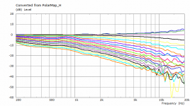
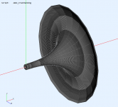
Umbrella horn (cca ⌀820 x 460 mm, 1.4") 🙂
Impedance is almost identical to a traditional exponential horn, but much 'cleaner' (less wobbly) due to the round over aka 'mouth termination'.
Classic horn freaks should love this.
Last edited:
Impedance wise, this is a 3,5k horn?
//
It's rather an 800Hz horn, I'd say.
Should go nicely with the HF10AK and I expect it to work well from 800Hz, at least in a hifi setting.
I see a lot of effort 🙂I've been working on optimizing an axisymmetric waveguide for the Dayton ND25FN-4 tweeter element, ...
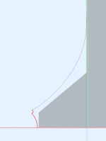
Did you model also the tweeter shape?
I see a lot of effort 🙂
Did you model also the tweeter shape?
Sure did. I don't have one on hand, but I was able to approximate the dimensions from their product drawings in the data sheet.
Attachments
I'd like to simulate the behaviour when made from segments like on the picture but unfortunatelly that's not how the mesh is generated anymore... Otherwise it would be easy to make such a horn from e.g. balsa (wood) stripes.... Classic horn freaks should love this.
(To explain - this is only a simplified visualiation in the CircSym mode; it is actually solved for a perfectly axisymmetric shape, not segmented like this.)
Last edited:
Well, a non-constant acoustic impedance could be compensated by a simple electrical equalization (including the time domain as these are all minimum phase phenomena I believe). You can't equalize directivity.
True that!
With FIR, even a non-minimum phase anomaly is correctable.
//
- Home
- Loudspeakers
- Multi-Way
- Acoustic Horn Design – The Easy Way (Ath4)