Same result than the Right channel..Prefect.
Now time to plug all the boards for the reel test. The last Picture with channel R and L 150 mV 1kz Input, Vol Pot Maximum
Eagerly waiting for pcb files of this preamp.
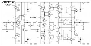
P30ZF test
Alright, without the THD measurement..no tools ready for that.
The only thing i am concerned about is the DC offset.
At the power on, the offset is around 3V going down very fast. After 20s we have around 200mV and after 45s 10mv, stable between -1 and +3mv after 1 minute.
Is there a possibility to have a better result ?
For now i added a I/O board with 30s Delay on time.
Don't be worry, i will post soon the gerbers file...need time
APEX P30ZF NEW VERSION STEREO September 2020 - YouTube
Last edited:
Crescendo Millenium Edition amplifier from Elektor isn't it?
Almost 40 years ago. Have you updated some parts or is it all from the first build?
Almost 40 years ago. Have you updated some parts or is it all from the first build?
Sorry, i just saw a typo..there is 2v not 3v at the power on.Alright, without the THD measurement..no tools ready for that.
The only thing i am concerned about is the DC offset.
At the power on, the offset is around 3V going down very fast. After 20s we have around 200mV and after 45s 10mv, stable between -1 and +3mv after 1 minute.
Is there a possibility to have a better result ?
For now i added a I/O board with 30s Delay on time.
Don't be worry, i will post soon the gerbers file...need time
APEX P30ZF NEW VERSION STEREO September 2020 - YouTube
P30ZF Spare Boards
I can offer 4 spare boards (P30ZF and Salas Ultrabib with apex On/Off) for my cost price, please PM if interested. First come first serve.
I can offer 4 spare boards (P30ZF and Salas Ultrabib with apex On/Off) for my cost price, please PM if interested. First come first serve.
P30ZF Offset
Mile, is there any way to adjust the DC offset at the power on. I would like to know, in case i have to adapt the board for an eventual modification, before posting the Gerbers file.
Thanks
Mile, is there any way to adjust the DC offset at the power on. I would like to know, in case i have to adapt the board for an eventual modification, before posting the Gerbers file.
Thanks
I have it shared here. You may download gerbers.
W61084ASN13_apex ax14_total new_2pairs_rev1- Share Project - PCBWay
let me know if its not convenient, I can post here as well.
regards
Prasi
hi prasi, i need transformer information pls. for 2 pairs.
thank you.
No,Crescendo Millenium is 20 years old🙂Crescendo Millenium Edition amplifier from Elektor isn't it?
Almost 40 years ago. Have you updated some parts or is it all from the first build?
I have built one channel.
hi prasi, i need transformer information pls. for 2 pairs.
thank you.
You can supply it with +/-56V.
For that a CT trafo of 40-0-40 VAC. if stereo , then atleast 300-400VA.
Mile, is there any way to adjust the DC offset at the power on. I would like to know, in case i have to adapt the board for an eventual modification, before posting the Gerbers file.
Thanks
Could you please describe what happens at power on and how long it happens?
As far I know it is to work togheter with A40 power amplifier and I am interested in both for long time.
TKS
Watch the videos, i beleive that is the best to figure out.
At the power on, with the original design, the offset is around 2V going down very fast. After 20s we have around 200mV and after 45s 10mV, stable between -1 and 3mv after 1 minute.
Apex P30zf Original Design - YouTube
I have add a 47k resistor at the right channel output parallel with the 1mOhm resistor (result 45k), the left channel is unchanged. that is that is much better.
Now at power on we have 1V and after 8s 0mV, stable.
Apex P30ZF Version adapted with 47k resistor add to the Output - YouTube
With 1khz and 150mV input signal
P30ZF Version adapted with 47k resistor- Test with 1kz - 150mV input - YouTube
Attachments
It looks like a power on/start up stabilization issue.
I suppose it can be solved with a power on delay relay.
If I understand well you are changing the load output resistor to optimise this issue.
If I remember well, this project is based in Marantz PM8005 and PM11 and the projectist changed the circuit with his own ideas. Maybe it is interesting to have a look in the original schematics.
Regards
Watch the videos, i beleive that is the best to figure out.
At the power on, with the original design, the offset is around 2V going down very fast. After 20s we have around 200mV and after 45s 10mV, stable between -1 and 3mv after 1 minute.
Apex P30zf Original Design - YouTube
I have add a 47k resistor at the right channel output parallel with the 1mOhm resistor (result 45k), the left channel is unchanged. that is that is much better.
Now at power on we have 1V and after 8s 0mV, stable.
Apex P30ZF Version adapted with 47k resistor add to the Output - YouTube
With 1khz and 150mV input signal
P30ZF Version adapted with 47k resistor- Test with 1kz - 150mV input - YouTube
You must test preamp with amp connect to output, amp input impedance load preamp with 22k... P30ZF DC offset is very good for circuit without global negative feedback.
Regards
It looks like a power on/start up stabilization issue.
I suppose it can be solved with a power on delay relay.
If I understand well you are changing the load output resistor to optimise this issue.
If I remember well, this project is based in Marantz PM8005 and PM11 and the projectist changed the circuit with his own ideas. Maybe it is interesting to have a look in the original schematics.
Regards
P30ZF is not based in any Marantz schematic. P30ZF is preamp schematic without global negative feedback.
Regards
P30ZF is not based in any Marantz schematic. P30ZF is preamp schematic without global negative feedback.
Regards
Thank you Mile to clarify it.
But if you compare complete schematics you will find lots of coincidences and of course some diferences as I pointed out.
Regards
Thousands of circuits share similarities with other circuits. That doesn't mean they were based on them.
Mile, it is possible to use pot. 100k instead of 10k pot.? If possible, what changes should be made?
Is it possible? I ask because I have good quality original 100k pots and I would like to use them. But if it is not possible, I will use the ones from aliexpress.
- Home
- Amplifiers
- Solid State
- 100W Ultimate Fidelity Amplifier