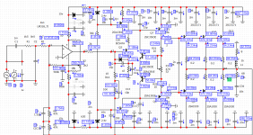
The current shunt also works perfectly on silicon transistors.When changing the schema . Post 86
https://www.diyaudio.com/forums/attachments/solid-state/872324d1598916210-unusual-amp-1987-a-1-png
https://www.diyaudio.com/forums/attachments/solid-state/872324d1598916210-unusual-amp-1987-a-1-png
have you tried to replace both BT308 and ZTX657 with another transistor, say BD140 and listen to it, i mean is the GT308B making the real difference in this amplifier?
1) In my build I tested ZTX657 and MJE340 for biasing. No difference.
2) Initially, I had 2N2222 in this place, and with its high Beta, it was causing bigger DC offset at the output (1V - 2V).
With MJE, offset went down to 2mV. According to the original article, beta of this transistor is not supposed to be higher than 100.
3) I tried BJT version with 'normal' biasing with single Si transistor (MJE),
and as far as I can tell - the sound and waves on the oscilloscope were the same. But I guess the differences might be too subtle to discover in such crude comparison...
To be honest - if I was building new amp, I would go for 'normal' biasing.
I don't believe that GT308 being Germanium or Silicon would matter for the sound.
The same way I don't believe that replacing feedback resistor with carbon type would make a real difference at the speaker 🙂
I guess that was also conclusion Stanislav1957 reached - he ditched Si/Ge biasing in his versions.
But I guess this doesn't prove anything..
More careful and detail testing of both versions of amps would be needed to compare.
My comparisons were only: oscilloscope and 5 minutes of random music playing on small speaker...
4) Biasing with both transistors being Si - won't work as in the original design, modifications are needed - see the beginning
of the thread.
Perhaps Elvee's version of biasing would be also good; I haven't tried it.
5) All my amps are being actively cooled by a fan controlled by temp sensor, so they run in relatively
stable conditions (for normal listening), with almost constant temperature of the
heatsink (except for extreme cases 🙂 ), so I don't care too much about biasing vs temp coefficient and accuracy of it.
Last edited:
The current shunt also works perfectly on silicon transistors.When changing the schema . Post 86
https://www.diyaudio.com/forums/attachments/solid-state/872324d1598916210-unusual-amp-1987-a-1-png
I tried exactly this kind of biasing with 2 Si transistors - in the sim.
Couldn't make it work....
Elvee's version of biasing with 2 Si transistors worked fine in the sim.
Last edited:
minek, stanislav1957, thank you for your answers.
minek, 160mA as stanislav1957 suggested is a lot, may be? I don't know.
Can you confirm if I can build this version or this version as you mentioned already, I am looking for a new Amplifier to build, myself I don't know which schematic to use, I don't want to buy these Ge transistors, I will scrifice with higher Bias on going 72 years back 😱 what do you think experts
minek, 160mA as stanislav1957 suggested is a lot, may be? I don't know.
I have mine biased at 100mA for now, but output devices are actually NOT running hot. Temp. is very acceptable, as far as I can tell.
Don't have problem with higher bias, it's not running as hot as class A 🙂
The question remains WHY such high idle current was recommended?
Is it really needed here? Sim doesn't have problem with lower current..
In my tests also everything was working/looking fine with lower idle current..
Now which bias scheme to choose from?
a) original Si + Ge
b) 1 Si ('what I call 'normal')
c) shunt version (2 * Si) - from Maxim (Stanislav1957)
d) Elvee's scheme
=============================
Safest is a) and b): I tested both, and amp works fine.
I guess Maxim built c), and also works fine for him, however I couldn't make it work in sim. Perhaps Maxim can recommend/explain ?
d) from Elvee has not been tried, but it looks fine in sim, and Elvee's ideas are always great, so if you feel curious and brave, go for it 🙂
I would recommend using schematic from post #136, with either of these bias schemes mentioned above.
Perhaps you can wait, and get Elvee's opinion, or for that matter, anyone else's (who is competent)?
minek, your feedback is highly appreciated. I think we can wait for other members answer as well, more hands can clap higher.
Now, I assume that this amplifier used that Ge to get away with lower Bias currents?
Now, I assume that this amplifier used that Ge to get away with lower Bias currents?
Q4Q5 and Q6Q7 must be of the same type . R21R22 affect the operation of Q4Q5. Current amplifier mode in the attachment
Attachments
Last edited:

Yes, with any of the biasing schemes described above, you can set idle current to whatever you want.Now, I assume that this amplifier used that Ge to get away with lower Bias currents?
I'm pretty sure it will work fine with 40-50mA.
Maxim mentioned that with Ge transistor, minimal current will be 15mA, so no problem here, as you will need usually more than 40mA.
minek, your feedback is highly appreciated. I think we can wait for other members answer as well, more hands can clap higher.
Now, I assume that this amplifier used that Ge to get away with lower Bias currents?
Use jfet instead of Ge. See posts 71 to 77.


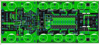
PCB LPK
Attachments
Last edited:

Last edited:
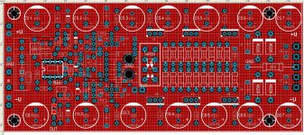
Here we go..
Metal,
GT308B has pinout BCE, not CBE, and pins are in-line, more like BD139,
not in triangle shape. Your PCB still may work, but you may want to re-align these pins a little..
Also, metal case of the GT308 is connected to the Collector, so I wrapped mine in shrink tube, to avoid shorting the case to other devices by accident.
- Home
- Amplifiers
- Solid State
- Unusual amp from 1987