Ah dammit.
I replaced q5, and it was all great! Measuring well, powered up slowly, all good.
Then while checking voltages, I managed to kill q2. I replaced it, and now the pins of q3 are starting to smoke.
Need to leave it alone for a night or two, then regroup.
Just to be safe replace Q4, then replace anything else you have killed.
Quick question while waiting for some replacement FETs to arrive -
What might cause the pins of Q3 to smolder and smoke, but not necessarily Q5, or the others?
What might cause the pins of Q3 to smolder and smoke, but not necessarily Q5, or the others?
Maybe they are smoking cause there is some kind or organic residue (flux maybe) on the pins of Q3 and not the other devices.
And by smoking - I mean overheating to the point of smoking.
Yeah - it's definitely a flux/solder smoke, so something's will cause those pins to heat up that much.
Yeah - it's definitely a flux/solder smoke, so something's will cause those pins to heat up that much.
This is why I say replace Q4.
It should be controlling the current of Q3 but it isn't.
You might have destroyed it some how while probing around.
It should be controlling the current of Q3 but it isn't.
You might have destroyed it some how while probing around.
Ah! Gotcha.
Well replacement transistors + fets should be trickling in. I'm going to move everything over to some clean PCBs. All this soldering/de-soldering seems to be causing the pads to lift.
Well replacement transistors + fets should be trickling in. I'm going to move everything over to some clean PCBs. All this soldering/de-soldering seems to be causing the pads to lift.
I'm mounting my Lovoltechs on top of the heat-sink flange. Out-of-the-box their legs aren't long enough for this, so they were shortened to just that needed for the horizontal bit, and then resistor leads were added for the vertical bit.
There's a brass bar behind the screw which is the same height as the JFET. It's stuck down with a bit of superglue to make assembly easier.
Then the JFET goes down with a bit of grease and mica and a cap screw with a conical washer and then a fender washer.
The MOSFETS mounted in conventional fashion:
While running it in it my benchtop PS claimed it was consuming 1.61A.
Temps measured with IR thermometer:
c-multiplier MOSFET case: 48ºC
CCS MOSFET case: 76º
heatsink nearby: 65º
cascode MOSFET case: 72º
JFET case: 44º
heatsink nearby: 40º
outside of heatsink at centre: 44ºC
Offset was at 21V so CCS should be burning 30W for a die temp of 101º.
All seems good enough to build the other channel?
Hi Jeff,
Just want to know how big is the washer you used in mounting the LU1014D?
Do you know they're genuine? (My possible fakes measured differently too, but they were on the low side; 0.8V - 0.9V IIRC.)
Does seem unusually high. Double-check the pinout and all your connections?
pretty sure that the pinout is correct
Do you know they're genuine? (My possible fakes measured differently too, but they were on the low side; 0.8V - 0.9V IIRC.)
I bought them from the member of this forum, not very sure that they are genuie or not
Hi,
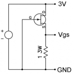
Just want to know how accurate of the 1 ohm resistor value will give the correct voltage value? My resistor was measured 1.1 ohm, not exactly 1 ohm. But I doubt that a 10% difference will give a 30% error on the voltage? What do you think?
Just want to know how accurate of the 1 ohm resistor value will give the correct voltage value? My resistor was measured 1.1 ohm, not exactly 1 ohm. But I doubt that a 10% difference will give a 30% error on the voltage? What do you think?
- Home
- Amplifiers
- Pass Labs
- F3 Builders Thread