Is your Quasimodo successfully verified on some other transformer? If not, then it could be that Quasimodo is not working properly.
I have just tried it on an Avel Lindberg 15VA #Y236001 torroid.
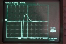
With Cx=.01uF Cs=.047uF Rs=9 ohms I get the trace on my scope shown on the attached photo.
Do those values seem reasonable? If so it seems to be a good result? Would this verify the Quasimodo board?
Attachments
Your CX is too small. Use the .15uf specified
The specified Cx is .01uF not .15uf? Correct? I think the specified Cs is .15uF?
Using those vale caps I cannot damp the ringing at all. I need to lower the Cs value considerably to bring the ringing under control. Then I get the strange trace shown in my original post.
I have just tried it on an Avel Lindberg 15VA #Y236001 torroid.
With Cx=.01uF Cs=.047uF Rs=9 ohms I get the trace on my scope shown on the attached photo.
Do those values seem reasonable? If so it seems to be a good result? Would this verify the Quasimodo board?
Yes, that are good results and Quasimodo is verified to work properly.
Is there anything unusual or “special” in construction of another transformer vs. successfully tested one? Are you sure transformer is OK?
"Yes, that are good results and Quasimodo is verified to work properly.
Is there anything unusual or “special” in construction of another transformer vs. successfully tested one? Are you sure transformer is OK?"
The other transformer is a custom made R-Core transformer made by Custom Magnetics. It is 5.4AH 120v single primary with 2X 18v secondaries. This is to be used on Salas SSLV 1.3 boards for +/-15Vdc duty.
The transformer has been tested both with an ohmeter and verified with AC applied to the primary.
In the thread “Quasimodo results” there are multiple R-Core transformer results for transformers rating 30VA and 120VA. They all successfully use Cx/Cs as 10 nF/150 nF. Maybe there is something different or unique in design of this transformer.
Current draw went way up...any ideas?
I am no expert by any means, but I would start with the part that switches the most current, the MOSFET, and test it and if it's a getting a signal to the base. You must have a O-scope. Hopefully someone more experienced will cut in.
In the thread “Quasimodo results” there are multiple R-Core transformer results for transformers rating 30VA and 120VA. They all successfully use Cx/Cs as 10 nF/150 nF. Maybe there is something different or unique in design of this transformer.
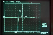
Just to back up a bit...I have now attached a shot of my scope display showing the trace using the recommended.
Cx=.01uF Cs=.15uF Rs=83 Ohms
That is about as good as I can get it using those default values.
Attachments
What happens with lower Rs values and did you check that trimmer pot is actually changing R value below 80 ohms?
Edit: ah yes you did, as there is 9 ohm result.
Edit: ah yes you did, as there is 9 ohm result.
Last edited:
I just checked the pot and it is operating normally. At lower resistance values the ringing just gets worse. Around 80 Ohms is the best damping I can acheive with the default values.
What happens with lower Rs values and did you check that trimmer pot is actually changing R value below 80 ohms?
Edit: ah yes you did, as there is 9 ohm result.
One thing I noticed that is strange is that when remove Cs from the circuit changing Rs still has an effect on the damping. Seems to me it should not as the snubber is now open?
I have attached a screen shot showing my trace with:
Cx=.01uF Cs=Open Rs=70 Ohms.
Again I can alter the trace with Rs even though Cs is removed from the circuit.
🙁Qmodo board just failed....
While result is fine, your transformer is still underdamped. For 500VA transformer, I would expect resistor value close to 10 Ω. Look at the picture from Quasimodo manual: optimal damping is red line. Your result is green line.
Yup....after replacing U2, I get 12.7...thanks mucho
Attachments
Last edited:
One thing I noticed that is strange is that when remove Cs from the circuit changing Rs still has an effect on the damping.
That shouldn’t be possible. Inspect PCB for unwanted solder bridges.
Well I feel really dumb!
I was for some reason under the impression that the .15uF Cs/C3 cap was socketed as is Cx/C2!
After chasing around on the Quasimodo board looking for problems I realized that the .15uF Cs/C3 cap is a surface mount cap and is not socketed. I thought Cs/C3 was located across the header from Cx/C2 on the other side of the header socket.
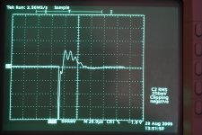
Now that I understand what is happening I get the trace shown in the image .
Cx=.0047uF Cs=.15uF Rs=60 Ohm
If I use Cx=.0068uF or .01uF I get a similar trace with a higher amplitudes of the peak amplitude.
I am still getting those little ringing peaks along the trace until it settles.
I was for some reason under the impression that the .15uF Cs/C3 cap was socketed as is Cx/C2!
After chasing around on the Quasimodo board looking for problems I realized that the .15uF Cs/C3 cap is a surface mount cap and is not socketed. I thought Cs/C3 was located across the header from Cx/C2 on the other side of the header socket.
Now that I understand what is happening I get the trace shown in the image .
Cx=.0047uF Cs=.15uF Rs=60 Ohm
If I use Cx=.0068uF or .01uF I get a similar trace with a higher amplitudes of the peak amplitude.
I am still getting those little ringing peaks along the trace until it settles.
Attachments

Those little ~120kHz squiggles are worrisome. But the whole waveform is a lot smaller - some 1/4 the size - than it was. (The Tek changed both the H and V settings from the earlier post.😉)
Are you still using the wire nuts and additional 7 inches of orange wires screwed into the terminals on Quasimodo? One of the handy things of those terminals is you can screw the wires of the transformer secondary that you're *ringing* right in to the board. Usually that much added inductance would yield a still higher frequency, and likely much lower amplitude. Still, I'd try it without the added leads.
Cheers
- Home
- Amplifiers
- Power Supplies
- Simple, no-math transformer snubber using Quasimodo test-jig