Thanks. So it did happen. But what about the voltage measurements? Are the voltages in your second schematic the correct ones?
Your measurement of output stage is correct, but see the distortion level:So i have 6.8v instead of 6v and 45 mA?
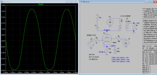
THD=1.5% @Pout ~1W
THD=3.85% @Pout ~2W
THD=7.5% @Pout ~2.5W
The bottom waveform is rounded quickly as you increase the input level hence distortion increased.
Attachments
Your measurement of output stage is correct,...
So you are gifted with the power of being able to measure circuits from a distance?
I believe the point Koonw is making is that the operating point generates a lot of distortion at low power. According to the tube sheets it is mostly 3rd harmonic which will not sound good.
The OP originally said the sound got bad at 1/4 turn on the volume pot. I showed how 1/4 turn could easily drive the amp to maximum output. Which would make it sound bad.
We do not have any information on the transformers so that could also be related.
Adding NFB will reduce the gain and improve the distortion.
Knowing the rms power output level when the amp sounds bad would help a lot in the analysis (maybe it is clipping). The small discrepancies on currents that you mention are not so important until we know if there really is a "problem".
If this were my amp I would try a voltage doubler and select a better operating point. In addition I would probably try the 6AU6 as a pentode with heavy schade feedback following one of Alex Kitic's RH84 designs.
Steve
According to the picture, the power transformer seems to be the small R-core 170V-130mA + 6.3V-5A 50VA low profile type from China. Hammond design guide suggest a 0.62 current derating when using a full wave bridge rectifier with capacitor input, this means that maximum DC recomended current draw is roughly 130 x 0.62 = 80 mA. The filament winding is not fully loaded, so maybe we can get away with 100 mA, but the transformer is right at the edge, and unable to supply at least 250V to bias the EL84 tube at the best working point. A voltage doubler with small capacitors and a big choke will give 300V at 40 mA on the PSUD simulation; that's enough for a single channel only, I believe.
I think it could be the clipping... from what pcan says, it would also be explainable ... I could reduce the current by following more closely the design of the Armstrong Stereo 55 which has 36 mA total and 5.5v on the cathode, with 150R resistor ... in this so I should be within the parameters that pcan gave me very kindly and have Less THD accordingly ...
Your measurement of output stage is correct, but see the distortion level:
THD=1.5% @Pout ~1W
THD=3.85% @Pout ~2W
THD=7.5% @Pout ~2.5W
The bottom waveform is rounded quickly as you increase the input level hence distortion increased.
I do not understand with what criterion spice gives as voltage on the anode 224v...
Thanks. So it did happen. But what about the voltage measurements? Are the voltages in your second schematic the correct ones?
It is useless to measure this as I have to re-calculate the amp stage parameters. Armstrong Stereo 55 has 36.6mA total and about 4mA on G2 ... I could lean on that project which certainly sounds very good ...
oh that is i used DCR 150 Ohms so less voltage drop, maybe it's 550 Ohms, can measure it? If you're interested in more sim just give a shout.
About the earlier sim, the rounding or clipping of bottom waveform is due HT is too low, need to increase (say 300V?) so moving it out of bottom clipping. Of course raising HT increased dissipation, but you can reduce the screen voltage to lower it. Together without cathode bypass you can get about 3W with < 2% distortion and reduced gain more with Gnfb. Read: The Valve Wizard -Single Ended feel free to raise any doubt.
For EL84, to be on safe side, total HT swing should not be greater than 550V
Last edited:
they are 500 ohm.
I only have this transformer, and I don't have room for a choke ... interesting tutorial, even if it's a bit complicated for the technical language in English
I only have this transformer, and I don't have room for a choke ... interesting tutorial, even if it's a bit complicated for the technical language in English
It is useless to measure this as I have to re-calculate the amp stage parameters.
Well, it could help you to learn how to measure a circuit properly.
If you are asking for advise on some problem in one of your builds and present a schematic with it, the least you could try is to present one with correctly measured voltages. And if you didn't measure it, you should have made that clear from the start of your topic.
Well, I think the best thing to do now is to reduce the screen voltage so that the total dissipation is about 5W, doing this the reduce current (~25mA) that is less taxing on PSU, but 2W of cleaner output. It's 140V for screen voltage in my sim to achieve that.they are 500 ohm.
I only have this transformer, and I don't have room for a choke ... interesting tutorial, even if it's a bit complicated for the technical language in English
oh that is i used DCR 150 Ohms so less voltage drop, maybe it's 550 Ohms, can measure it? If you're interested in more sim just give a shout.
Shout:
I would be interested in simulating this...
Attachments

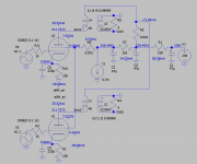
There is something wrong with me ... these are the measurements I made this morning (the measured data are in pink)...
Attachments

Last edited:
"other measurements:
plate El84: 188v
cathode El84: 4v3
plate 6AU6: 73"
Increase the voltage of both tubes! Have a look into the data sheets for the standard operating points. EL84 is 250V (plate to cathode) / 250V g3 / -9V at the g1 (=cathode)
plate El84: 188v
cathode El84: 4v3
plate 6AU6: 73"
Increase the voltage of both tubes! Have a look into the data sheets for the standard operating points. EL84 is 250V (plate to cathode) / 250V g3 / -9V at the g1 (=cathode)
... these are the measurements I made this morning (the measured data are in pink)...
Looking only at the voltages in pink, this is the way I analyse it.
I see that you went back to using 3 x 220 Ohm after the rectifier.
With 3 x 220 Ohm: I = V/R = 5/73,3 = 68 mA
With 2 x 220 Ohm: , I = V/R = 5/110 = 45 mA (which would not make sense).
The screen grid current of 2 x EL84 and the current of 2 x 6AU6:
Rtot : 1/2200 + 1/2700 = 1/Rtot, so Rtot = 1212 Ohm
I = V/R = 17/1212 = 14 mA
So 2 x 6AU6 = 6 mA (3 mA per 6AU6)
So 2 x Ig2 = 8 mA (4 mA per EL84)
The current that is left for the anode currents of 2 x EL84 = 68 mA – 14 mA = 54 mA, so Ia = 27 mA per EL84.
Rdc primary OPT = about 400 Ohm (or?), so taking in account the voltage drop over the primary: Va = 204 – (0.027 x 400) = 204 – 11 = 193 V
Vg1 = Ik x Rk = (0.027 + 0.004) x 150 = - 4.6 V
So Vak = 193 – 4.6 = 188.4 V
Vg2k = 187 – 4.6 = 182.4 V
Looking at page 7 of this datasheet for the EL84 ( http://frank.yueksel.org/sheets/030/e/EL84.pdf ), I am having a hard time understanding how the EL84 could only be passing 27 mA at Vg2k = 182.4V and Vg1 = -4.6 V.
The curves on page 7 are given for Vg2 = 250 V (and Va = 250 V) and Vg2 = 210 V (and Va = 250 V). Note that between the two curves, and at Ia = 26 mA, there is about four blocks of the x-asis difference. To get the curve for Vg2k = 182.4 V you have to shift the curve for 210 V about three of these blocks to the right. If than you look at which Vg1 fits with 27 mA on that curve for Vg2k = 182.4, you end up at about -6 V.
At Vg1 = -4.6 V you would wind up with an Ia of some 40 mA.
The fact that in your amp Vak = 188.4 V instead of the 250 V in the curves, would explain part of the lower Ia, but unless I am mistaking, it could not explain the difference between 40 Ma and the 27 mA in your amp.
In your schematic the anode dissipation of the EL84 = Vak x Ia = 5.1 Watt. So with the losses in your OPT you will have a hard time getting 2 Watt out of it. But others already pointed that out to you.
Last edited:
- Home
- Amplifiers
- Tubes / Valves
- EL84 SE with 7000 OT