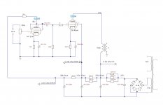
If the transformer is from a standard tube radio, the usable power is only 2-3W, and less than 1W at 100 Hz. But: You said there is distortion regardless of the signal strenght. This could be a issue of the 6AU6 stage. Have you tried to use it in pentode mode with the datasheet values? It might not sound the best, but it's a good place to start. I attach the GE datasheet table. Check the values Ebb=180V.
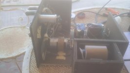
they are two good vintage Audax OT taken from two old amplifiers ... the size I think can hold 4-5w, certainly with a frequency response not particularly extended ... the old amps still sounded more than decently.
Besides your use of the quotes (you've put your comment inside the quote), how about new, accurate measurements? There is now this 26 mA (so 26%) of the 100 mA unaccounted for.
In triode mode the 6AU6 has a gain of 36
I don't think so. The amplification factor of the 6AU6 in triode mode is 36, but that's not the same as 'gain' (but they are related ofcourse).
With a load resistance of 39K, a grid resistor of the next stage of 220K, and a supply voltage of 200V (like in the schematic) I think you will have a gain of about 24.
PCL200
Correct, the actual voltage gain will be less than 36.
My point is that ~200mv is required to drive the EL84 into clipping. If he was driving this with a CD player than 1/4 turn on the volume pot is sufficient drive for max power out.
Until the OP measures the power output or looks at an oscilloscope trace when the sound goes bad we don't know where to look to solve the "problem". Or if there even is a problem.
Steve
Maybe it's what you have built, but still your measurements can't be right.
The EL84's now take 40 mA each (the cathode current is 40 mA, which contains both the anode and the screengrid current). So 80 mA total, so 16 mA of the now 96 mA would have to flow through the two 6AU6's, so 8 mA per 6AU6.
But in your updated schematic, the 6AU6's are taking 3 mA each.
So 10 mA is still 'missing'. What is going on here?
It gets weirder and weirder... Measure it, instead of asking me. You said you have really built it.
And no way the EL84 is going to pass 45 mA at Vg1 = -6.8V and the Vg2 indicated in your schematic.
And no way the EL84 is going to pass 45 mA at Vg1 = -6.8V and the Vg2 indicated in your schematic.
Is there any chance to get another power transformer and/or replace the three paralleled resistors by a suitable choke, both in order to raise the plate supply voltage to about 270 Vdc? If so, increase the cathode resistor to 210 ohms and you'll get about 4.5 watts of output power.
It is also wise to apply the other suggestions given yet, especially to apply some GNFB.
Best regards!
It is also wise to apply the other suggestions given yet, especially to apply some GNFB.
Best regards!
I have a very peaceful Armstrong Stereo 55 receiver that works with 210v anode and 208v s.grid without filter choke, 7000 OT ... the differences are that it uses an EZ81 for rectification and obviously a preamp circuit with much higher gain. It also has an NFB. By apply the other suggestions, do you mean inserting an NFB or re-drawing the second circuit?
.... but when I turn the volume up over 1/4 of its drive it starts to distort, .......regardless of the strength of the incoming signal ... what's wrong?
Is the incoming signal controlled by another preamp? How do you reduce the incoming signal from a CD player that has a high output to start with?
I tried to inject a variable source ... even at the minimum the distortion starts the same at 1/4 of the volume.
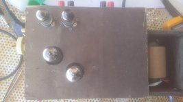
Pics. ..
Attachments
Last edited:
I tried to inject a variable source ...
Of music, or what is the source? What is its output impedance?
Oh, you've got very bad weather, haven't you?
Best regards!
Sunny But cool, why?
A CD Player with fixed and variable output...
Your CD player is expecting a normal 10K ohms line level input impedance not a 100K volume pot.
- Home
- Amplifiers
- Tubes / Valves
- EL84 SE with 7000 OT