Net of my usual mistakes, I could do something like that, what do you think about?
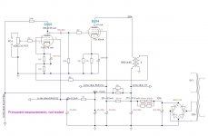
The way you connect the 6AU6 now will give you a gain of about 150. I'm pretty sure that your OPT's are not good enough to apply so much GNFB that this surplus of gain can be traded in for better quality. Of course you can limit the input voltage with the volume pot, but because of this high gain after the pot, I expect the amplifier to be a bit noisy (hiss, or in fancy terms: partition noise). You can't move the volume pot to the powerstage and have GNFB at the same time.
Beside (again) many of the voltages/currents not obeying Ohm's Law, you should skip the connection parallel to the 220 Ohm resistor in the cathode lead, but that's probably a drawing mistake.
Apart from the wrong parallel, this time I just can't see the miscalculations 😕...
in the amplifier from which OT were taken there was a GNFB starting from a triode gain of about 60 ... I could go back to configuring 6AU6 in triode and do some tests to see if it has a beneficial effect or not ... in this so I'm not forced to vary the driver parameters and not go crazy again in the connections in so little space available.
Two of them:
The cathode resistor of the EL84 is 165 Ohm (= 2 x 330 parallel). The cathode current is 41 mA. V = I x R = 0.041 x 165 = 6.8 V. But the schematic says 7.5 V.
The cathode resistor of the 6AU6 is 2420 Ohm (actually a fraction less because the feedback resistor and the secondary are in parallel with the 220 Ohm resistor). V = I x R = 0.00055 x 2420 = 1,33 V. But the schematic says 1.8 V.
Why don't you pick a proven schematic with tubes you have, or which you can get your hands on, an build that?
Two of them:
The cathode resistor of the EL84 is 165 Ohm (= 2 x 330 parallel). The cathode current is 41 mA. V = I x R = 0.041 x 165 = 6.8 V. But the schematic says 7.5 V.
The cathode resistor of the 6AU6 is 2420 Ohm (actually a fraction less because the feedback resistor and the secondary are in parallel with the 220 Ohm resistor). V = I x R = 0.00055 x 2420 = 1,33 V. But the schematic says 1.8 V.
Why don't you pick a proven schematic with tubes you have, or which you can get your hands on, an build that?
Accustomed to the triodes with which plate current corresponds to the cathode current I marked the plate current on the cathode.
I would not be able to justify all the hours spent trying to understand if I took an already tested pattern ... as I always did in my life, such as with the guitar, I started from scratch to learn how to write my own songs, not to play others' songs ... I realize that this is quite presumptuous, but this is my character and these are my ways of learning ... I do it by trying and trying again, often making mistakes ... sure, making mistakes in electronics is definitely more dangerous than to mistake a guitar chord ...
Attachments
I think I understand what you mean. I teached myself (more or less) to play (in 'historical order') electric bass guitar, electric guitar, electronic drums and keyboard. It’s the same for my knowledge of tube electronics (I rediscovered this great hobby about 14 years ago).
If you send me a PM with your name and postal adress, I will send you, if you want, and charging you only the delivery costs (I think something like 16 Euro’s, but I have to dive a bit deeper in that):
- A power transformer, salvaged from a Philips BX653A radio (see: http://www.philipsradios.nl/Schemas/BX653A.pdf ), which for sure will give you way enough voltage and current for 2 x EL84. I’m sure it will at least deliver:
270-0-270 V / 125 mA
6,3 V / 3 A
6,3 V / 1,6 A
- Two tested EZ80's to go with the power transformer. The two tube sockets for the two EZ80's are mounted on the power transformer itself. You could connect them so that each EZ80 is feeding one channel of a stereo amplifier.
- Two output transformers (NOS; intended for the Erres KY576CW radio; see attachment) with the following specs:
Brand/type : Van der Heem GK 51475
Primary impedance : 5K Ohm
Secondary impedance : 4 and 6 Ohm
So with 8 Ohm speakers on the 6 Ohm connections, the primary impedance will be 6K7, which in real life is close enough to 7K.
That would give you some more room to try different designs/ideas. And I have way too much stuff anyway (I'll never get all of it used in my future projects).