A very interesting variant of the darTZeel NHB-108 clone with two pairs of power transistors, for each PCB, that I just finished making.
Clearly having the same driver stage as the normal version, the output power is substantially identical, but the power amps working in a zone of greater linearity, return a register of "bass" with the same speed and articulation of the normal version, but much more dynamic and impact.
The changes I have made are as follows:
1) for a more suitable drive of the two pairs of power amps, the replacement of the two 5.1 V Zener diodes Z1 and Z2 of the "Constant Current Generator" of the driver stage originates, with others of 6.2V (maximum applicable value to avoid the saturation and distortion of the Q9 and Q10 drivers) to have a better and more adequate drive capacity of the final power stage;
2) The installation of a Supercap with a higher capacity of 30,000 uF between resistances R9 and R10 and mass, replacing the classic 22,000 uF;
3) The replacement of the four original capacitors of ridiculous quality (C17/C18 330uF/35V and C15/C16 47uF/100V) with others 470uF/50V and 47uF/100V respectively of the excellent and extraordinarily musical NICHIKON Muse UKZ Series;
4) And finally, perhaps the most important thing of all for this exceptional circuit layout, the perfect match and coupling for HFE, of the four input 2N5551/2N5401 transistors (Q1, Q2, Q3 and Q4 that you must be careful to physically join with a little thermal paste and the heat-shrink sleeve), in order to reduce the characteristic of this design of the DC Offset output, "dancer" and unstable;
Hi ! analog sa I changed the Zeners to 6.2 v. Maybe I should try 5.6 instead. I will measure voltage drop over R 19 and 20 later today. Rail voltage is 55 vdc
Last edited:
The higher voltage zeners will simply increase the bias of the drivers and outputs. If your sinks can take it it's fine.
This is the 1kHz into 7.4ohm distortion i measured at 140W. It is perhaps comparable to what you get when you take into account it is only two pairs.
Hi, I think that when you're doing measurements, you should adjust the measurement attenuator to al least - 12dBFS.
Like this on your attachment pic, you have - 21.3dBFS so real measured distortion could be higher or lower than real value, I've seen both examples in experimenting measurements with Arta.
Could you measure thd vs freq.?
The higher voltage zeners will simply increase the bias of the drivers and outputs. If your sinks can take it it's fine.
My problem on the faulty channel was damaged PCB. Hope I can repair it
There was only 0.5 v over one 6.1 v Zener.
Problems occured because I mounted wrong Mje 2 places. 🙁
Hi, I think that when you're doing measurements, you should adjust the measurement attenuator to al least - 12dBFS.
To tell the truth i have not noticed any significant difference except perhaps in noise. Shall double check.
The PS is in use in another amp atm, maybe over the weekend can take some more measurements.

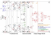
Anyone knows what is the reason for using diodes at the bases of output bjts, or diode in parallel with resistor like in the first model?
It's explained in the patent. "The diodes provide a very fast pulse response and protect the resistors against overheating" 🙂
I guess removing the diodes won't make any difference.
I guess removing the diodes won't make any difference.
The resistor connected to the base of final transistors sets the bias of the output stage, the lower value, the higher the bias.
The two CCS deliver about 115mA to drive the final stage. At 115mA and full power, the voltage across the resistors would be 2.3V that means 265mW and loss of driving capability. Using a lower value resistor you could obtain a better driving capability buth the final stage would be overbiased. The diode is the solution: you set the preferred bias using a suitable value (20Ohm) then put a diode paralleled to the resistor; over 0.6V across the resistor, the diode starts conducting so the driving capability is full across the diode, without affecting the idle bias.
The two CCS deliver about 115mA to drive the final stage. At 115mA and full power, the voltage across the resistors would be 2.3V that means 265mW and loss of driving capability. Using a lower value resistor you could obtain a better driving capability buth the final stage would be overbiased. The diode is the solution: you set the preferred bias using a suitable value (20Ohm) then put a diode paralleled to the resistor; over 0.6V across the resistor, the diode starts conducting so the driving capability is full across the diode, without affecting the idle bias.
The resistor connected to the base of final transistors sets the bias of the output stage, the lower value, the higher the bias.
The two CCS deliver about 115mA to drive the final stage. At 115mA and full power, the voltage across the resistors would be 2.3V that means 265mW and loss of driving capability. Using a lower value resistor you could obtain a better driving capability buth the final stage would be overbiased. The diode is the solution: you set the preferred bias using a suitable value (20Ohm) then put a diode paralleled to the resistor; over 0.6V across the resistor, the diode starts conducting so the driving capability is full across the diode, without affecting the idle bias.
And such a large value base resistors are used to prevent thermal runaway I guess. Btw, that "fast pulse response" thing sounds funny 😁
So it is true that diodes prevent 20Ohm resistors against overheating (18mW instead of 265mW). But this could be resolved using 1W resistors. It is false that diodes provide very fast pulse response because, when the driving voltage goes below 0.6V the final transistors are still driven, upon their threshold, across the resistors.
False or not the US patent office found it was patentable 🙂
Haha.. No comment
What?
So what is this, please? NHB 108 version 2? 458/468?
Or your own design?
Try this, look at the schema. Because of increased voltage up to 140V and added final stage, it should deliver at least 200W on 8Ohms. Mine has 11 couples of transistors. The sound on Acoustat 1+1 is outstanding!
So what is this, please? NHB 108 version 2? 458/468?
Or your own design?
NHB108 200W
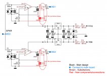
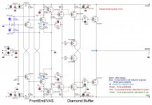
This is an add-on to the original schema made by me. I decreased the CCS current from 115mA down to 46mA, a lot more than enough to drive the new final stage to its full power. The rest of the circuit is original, just changed capacitors on power line because increased voltage, and replaced alll ceramic capacitor with silver mica ones. Green 0Ohm resistors could be increased, with caution and a variac, to have an higer bias but, just with a bridge, I cannot hear any crossover distortion. My function generator and oscilloscope are elsewhere and cannot trim the bias perfectly. The output stage is polarized in NSCB, transistors never switch off.
This is an add-on to the original schema made by me. I decreased the CCS current from 115mA down to 46mA, a lot more than enough to drive the new final stage to its full power. The rest of the circuit is original, just changed capacitors on power line because increased voltage, and replaced alll ceramic capacitor with silver mica ones. Green 0Ohm resistors could be increased, with caution and a variac, to have an higer bias but, just with a bridge, I cannot hear any crossover distortion. My function generator and oscilloscope are elsewhere and cannot trim the bias perfectly. The output stage is polarized in NSCB, transistors never switch off.
So it is a modified NHB-108?
Did you just change some components on a regular NHB board, or did you design your own board?
Are you using a chinese Midpoint Servo board? ("Connect to midpoint servo")
Picture?
Did you just change some components on a regular NHB board, or did you design your own board?
Are you using a chinese Midpoint Servo board? ("Connect to midpoint servo")
Picture?
Last edited:
Yes, it is a modified NHB-108. I had a couple of very good quality 625VA, 50+50V toroidal transformer, and a lot of MT200 Sanken doing nothing so I had to find a job for them. I bought the bare pcb of the NHB-108 on eBay and put components on it. I had hard time to get it working because of fake transistor MJE15032/3 bought on eBay; I almost renounced. Then I started buying electronic parts from official dealers and the problem was resolved. I am using the Chinese midpoint servo with a light modification in the output, I'm posting the schema here, as well some pictures. The complete power amplifier is a dual mono, no common ground. The cabinet is a 5 Unit "Dissipante" by HiFi2000, capacitors are 24x6800uF.
Attachments
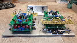

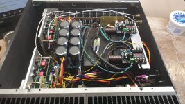
OMG Massive heatsinks and a ton of capacitors and power transistors! 🙂
I am just confused by the amount of output transistors. On the schematic you added two pairs but in your amplifier you have 10 pairs?
But how many are really needed? For one thing it is a total departure from the design philosophy of very few components in the original NHB 108. NHB 468, on the other hand have several pairs of output transistors, so..
Yet all this sounds good? Airy OR Powerful?
How many output pairs are really needed? Since there is no feedback loop departing from the speaker, the more, the better for the damping factor. I had a bunch of MT200 so I used 11 pairs a channel. Referring to the schema, watch at the connecting lines between the first and the second pair, lines are dotted, it means you can put other pairs in the middle, I intended to leave the shema as simple as possible. When I chose the NHB-108 I didn't care about designer's philosophy of very few components, the first goal was to search for a circuit with no esternal feedback loop, the second goal was to use the bunch of MT200 and the two power transformers, and, last, to have at least 200W output power on 8Ohm. Using the NHB-108 is very simple even because you can buy the pcb. In my opinion, there are some points to be tested for improvement but, having fake transistors, nothing worked while studying on modifications. When I understood that the cause of failure was those fakes, it was too late to start again with experimentation so I gave up in changing anything in the original circuit. Then the designer philosopy is not that altered, the ciruitry defining the sound is unchanged. Actually there should be an improvement because the former final stage (here used as driver stage) now works no longer in B class but in A class and the output pairs work in non switching class B, transistor never go off, not even during opposite semy-cycle. Since I didn't want to continue experimenting, I remain curious on one thing about the two CCS: AR, in its D400 uses dynamic CCS that could conceptually be implemented in a very easy way on a modded NHB-108 in order to raise the output power with an increased voltage, without wasting in heat a lot of energy. But I have no more time nor wish to start again. Imagine that, after all failures, I started working on the LJM L20 V9.2 adding a buffer to the VAS, replacing Rs and C in order to better define the feedback loop, replacing the output resistors from 0.2Ohm to 0.1Ohm, adding a coil to connect the speaker, replacing the output pairs with mine 11. The result was a very good sound. But not good enough for my Acoustats, very hard to be driven in presence of external feedback loop. Then came the illumination about fake transtistors. So, how the WOTS-WHA 216 (Warmth Of The Sound - Will Hear Again, being 216 just the double of 108) does sound? First of all it is better to frame the whole chain: the preamplifier is an Aikido, original design (pcb design of mine) modded only to set tubes in a different phisical way, in order to separate lower from higher heathers, and the heathers are polarized a bit positive with respect to their cathodes; it has a tube rectifier, stabilized power supply with Virtual Battery double circuit; the speakers are the Acoustat 1+1 Red Medallion with interpretation of mine of the C-Mod, while (do not be surprised), the source is the original, incredible sound card of the Gigabyte GA-970A-DS3P motherboard. I think the WHA-216 is one of the best main amplifier (at a human cost) I have heard during my frequentation to lots of HiFi Galas. It is sharp but smooth at the same time, it does not move itself a bit, it moves the speakers. Hard to find words to define the feelings, goose bumps in some musical passages, surely listening at Il Volo, when they all 3 sing together with their different voices, or listening Susan Boyle voice, or Rachel Podger's Estro Armonico, or Perpetuum Jazzile (Abba's medley). At least, I'm very happy and do want to rest for a little time. I enclose a schema with the very simple starting point to experiment dynamic CCS, someone could like it and start a new project.
Attachments
- Home
- Amplifiers
- Solid State
- Dartzeel amp schematic - build this?