It's such a pity that you didn't apply for a design role at Nakamichi in the 80's...They might have been way better than they were with you on board, perhaps being able to apply to Intergalactic Patents too!
Nothing to do with ego and everything to do with better components and a more thorough general understanding of how to design for low noise.
Remember, as far as feedback went, in 1980 most designers were just emerging from the dark ages although there were a few that really understood it as applied to audio (and no, Dr. Matti Otala did not understand it). The same for low noise design. There were as far as I can tell, very few that were masters of the art.
Thankfully, that expertise has now percolated through to mere mortals like you and me.
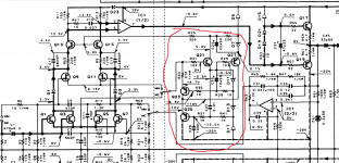
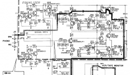
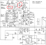
Here's something for a genious that's able to understand this circuit function (the one circled in red) without reading the service manual. For those who don't think of themselves as the best designers in the Universe i'll send the service manual that explains everything 🙂
Attachments
Post #98
Terrible. Over complicated, pretentious, completely lacking in elegance and can be done with a fraction of the components today. This is the problem with audio. When people cook up circuits like this, it’s no longer engineering but performance art.
People have tried to explain to you and others that the cartridge is the thing that in any competent MM pre design ultimately limits the performance. Designing circuits that ignore the reality of the noise contribution of L and R fall short on performance and topological elegance.
Anyway, I can add nothing more here and will step out for a while.
Well, i'm not sure that i needed to be explained that thing...but i enjoy seeing people over reacting 🙂
Post #98
Terrible. Over complicated, pretentious, completely lacking in elegance and can be done with a fraction of the components today. This is the problem with audio. When people cook up circuits like this, it’s no longer engineering but performance art.
Is it the MM / RIAA part of this circuit that you find over complicated or the MC pre amp?
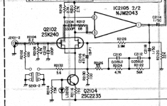
Sure, the 2sk240 is low gate-source capacitance and one could argue that that cascode is not needed, but I believe that in general, cascode is good for JFET MM input stages.
http://www.linearsystems.com/lsdata/others/LSK489_Application_Note.pdf
Dreamth: Have you looked at the RIAA used by NAD in the S100. I beleive you will find it to you liking. Two stage amplifier with passive LP and active HP RIAA shaping. BJT based LTP input with different current in the input pair depending on MM or MC configuration. Op map based second stage.
Well, i'm not sure that i needed to be explained that thing...but i enjoy seeing people over reacting 🙂
So you admit you are trolling? Well, at least you are honest about it.
Another way to look at this is the 47k load resistor is shunted by the series combo of the cart resistance plus its L. At LF the preamp sees the cart R in parallel with 47 k load R. As frequency increases, the L increases and the total source seen by the preamp increases so at 20 kHz, it can be 10-15k Ohms. You have three noise components: noise voltage of the amplifier, noise current x source resistance and finally thermal noise contribution of the resistive part of the cart. All these sources add up RMS style for the total equivalent input noise.
With a JFET input pre, there is almost zero noise current, only noise voltage, unlike bipolar where the noise current can be quite high. So the noise current x the total source resistance part effectively is not there and this is why JFET input stages make good MM phono preamps provided the noise voltage is low - there are some very good devices in this regard like BF862 (discontinued now) and LSK389
It's a matter of accounting really, but I would say that the termination resistor is part of the phono amplifier and that therefore any amplifier with a plain old room temperature 47 kohm termination resistor has an equivalent input noise current of at least sqrt(4 k T/47 kohm) ~= 0.5869 pA/sqrt(Hz). With a JFET or valve input, that's pretty much it, while bipolar designs can be far worse than that.
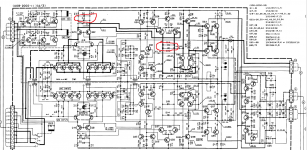
I don't see any cascode in the mc section in CA-7 but CA-5 and SR4 were made by the same company at the same time during the contract they had with Treshold...they are just different flavors for different money...the same as todays most acclaimed designs but noone will disconsider the phono section in SR4 or CA-5 just becuase they had built on a bufget...They are much better than many other preamps.Is it the MM / RIAA part of this circuit that you find over complicated or the MC pre amp?
Sure, the 2sk240 is low gate-source capacitance and one could argue that that cascode is not needed, but I believe that in general, cascode is good for JFET MM input stages.
Yet i wanted to show that in 1987 they knew how to make a sucessful MC input with just one 2sk170 in CA-5 ...while they showed the complete opposite in CA-7 same year.
As for the Nad S100 ...not bad at all at a first glance, extremely low noise PNP transistor, probably extinct, but for DIY i stick with their previous design in 2030 at least for the mm section...
Another design i really liked was one that i found in a scraped HK that i never had the opportunity to listen...
Attachments
I wouldn't dare put valve preams next to fet preamps just because i built one of the best valve preamp already and listen to one of the lowest noise paralleled fet input designs from DENON and it didn't impress me , but if i can't hear a clear cut difference btw bjt and fet input i don't care...I hope' ill try the synthesized load version with fet input this year cause you realy made me curious about it .Unfortunately i can't afford to build Scot Wurcer's fet preamp variation cause it looked interesting for its soft clipping behavior to try.With a JFET or valve input, that's pretty much it, while bipolar designs can be far worse than that.
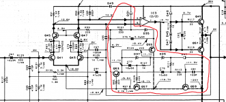
The schematic in post 98 is not exactly high res, and maybe i'm misreading it, bit isn't Q129/130 and associated components forming a cascode to avoid capacitive loading due to Miller effects?
I am more concerned by un-linear effects on capacitance and cartridge loading than the absolute value.
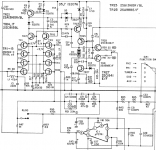
Attached is 2 more 80's examples of mid-end (Luxman 103) and more advanced (Denon PRA1100) JFET input RIAA solutions. The Denon is my best sounding RIAA so far, but unfortunately has one big drawback. Clicks and pops caused by surface damage that goes unnoticed on two stage solutions like Parasound P5 or REGA Fono-MM can be quite obvious on the Denon.
Haven't fired up the S100 Stage yet, but if I'm not happy I will look towards an RJM Emerald project with AD743 input amp. Also very intrigued by the upcoming design from Bonsai
I am more concerned by un-linear effects on capacitance and cartridge loading than the absolute value.
Attached is 2 more 80's examples of mid-end (Luxman 103) and more advanced (Denon PRA1100) JFET input RIAA solutions. The Denon is my best sounding RIAA so far, but unfortunately has one big drawback. Clicks and pops caused by surface damage that goes unnoticed on two stage solutions like Parasound P5 or REGA Fono-MM can be quite obvious on the Denon.
Haven't fired up the S100 Stage yet, but if I'm not happy I will look towards an RJM Emerald project with AD743 input amp. Also very intrigued by the upcoming design from Bonsai
Attachments
Last edited:
Well it happens that pra 1100 was the exact DENON preamp model i listened...It was fine , nothing wrong with it, but really boring...The cascoding concept was better explored in Kenwood L-02A, LA-1, kenwood KA-2200
2SK 369 has an input capacitance of 75pf, four of them in parallel plus the input cable capacitance will overoad the mm cartridge... Using just one pair of fet transistors for mm input makes more sense.
2SK 369 has an input capacitance of 75pf, four of them in parallel plus the input cable capacitance will overoad the mm cartridge... Using just one pair of fet transistors for mm input makes more sense.
Last edited:
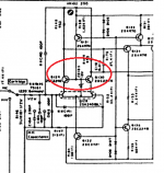
that is in the mm eq sectionThe schematic in post 98 is not exactly high res, and maybe i'm misreading it, bit isn't Q129/130 and associated components forming a cascode to avoid capacitive loading due to Miller effects?
You're the first one to talk freely about this effect in this topic so i need to Congratulate you because all the "ultra low noise" advocates are simply ignoring a very real and annoying aspect.This is why mainly valve preamps rule in the phono world!The Denon is my best sounding RIAA so far, but unfortunately has one big drawback. Clicks and pops caused by surface damage that goes unnoticed on two stage solutions like Parasound P5 or REGA Fono-MM can be quite obvious on the Denon.
In kenwood you have 2 sets of soft clipping diodes while in denon you only have one set.In denon you have also a higher gain first stage so i suspect that those diodes are getting hard clipping, unless TR21 -D9 combination isn't the killer one.I'd try changing Tr21 for MPSA18 or 2n3906 for their quasi saturation component which will make it loose current gain, but then D9 , a 3.3v zenner might need to be raised to 6v2 and there's a fine balance there...i'd try a simulation to see what can be improved there although some other guys might be better at that than me.
Maybe this topic will help you a bit by throwing the second cascode in the vas and replacing the whole topology with a Lender like VAS:
Some Fisher CC-3000 mm phono mods
Attachments
Last edited:
If you're using an mm cart, unless you have the 2sk389 version input you can also do a very simple trick: just remove 3 pairs of 2sk369 and that saturation might be much softer.If you have 2sk389 you can only remove two pairs.R9 -R11 might need to be replaced with 150 or 100 ohms too but you can leave it for the moment
Last edited:
It's a matter of accounting really, but I would say that the termination resistor is part of the phono amplifier and that therefore any amplifier with a plain old room temperature 47 kohm termination resistor has an equivalent input noise current of at least sqrt(4 k T/47 kohm) ~= 0.5869 pA/sqrt(Hz). With a JFET or valve input, that's pretty much it, while bipolar designs can be far worse than that.
Fully agree!
What happened?Did you forget anything here?Anyway, I can add nothing more here and will step out for a while.
Or maybe... Alien Vs Predator - Enemy of my Enemy is my Friend (2004) - YouTube
Dreamth: Thanks for all advice on the Denon. Im using a REGA pickup with low DCR/inductance and a rather high 7mV nominal output so I will check out modifications according to you advice.
I have been deliberating how to but in a servo with better DC precision and getting rid of C33. Removing some transistors will at least rid me of the electrolytic capacitor!
Anyway, the last posts on overload margins and "historical" implementations may be veering of topic with respect to the original topic of BJT vs JFET input stage.
Also, I think everybody here agrees that noise in not the only parameter worth considering (although it may be one of the easier ones to predict). Channel balance, overload margins, line driving capabilities and others are also important factors for a complete RIAA design, although FET vs BJT input may not be a significant contributor to these parameters.
My thoughts and conclusions so far are:
JFET pro: Better performance compared to BJT for current noise, particularly important for MM pickups. Direct coupling to pickup without risk of DC current tru pickup possible.
JFET con: Linear and un-linear Miller capacitance influencing pickup loading unless cascode is used. One or two parallel transistors typically needed for MM. Two or more for MC, making "switched MM/MC input sections optimized for one or the other unless one add complications of switching transistors in/out of circuit. Quality JFET for audio getting increasingly difficult to find of the shelf for DIY. Particularity for full complementary N-FET/P-FET inputs.
BJT pro - Better voltage noise simplifying MC circuits. Cascode circuit optional due to base input capacitance typically being much lower compared to FET. The best types (like ROHM) may not be available anymore, but still more options for DIY compared to JFET.
BJT con - Current noise characteristics vs voltage noise dictate different optimal operating points depending on MC or MM. Input bias current typically dictate capacitor input unless complementary input stage with carefully matched NPN/PNP transistors are used.
With respect to choice of input device, other issues I would like to see further discussed: Cartridge loading vs frequency. Distortion characteristics/spectra and need for feedback. Clipping/overload characteristics. Does a single "all in one" RIAA like e.g. the Denon stage discussed have different requirements compared to a two stage RIAA like the NAD S100?
How quiet must a input stage be? I have often seen references to approximately 70 dB surface noise on 33 RPM discs, but what are the noise and overload requirements if I'm playing albums on modern 45 RPM pressings?
I am still looking for that "ideal" two stage MM RIAA design where both current noise and voltage noise is low enough so that RIAA noise is well below record surface noise independently of high impedance/inductive cartridges are used or if using low impedance High Output MC cartridges.
I think there are a few other topics discussing cartrige loading vs frequency for a long time ...
I can't see the use of splitting the riaa network when passive.It may be useful with op-amps active or active -passive network combinations to fight overloading with low supply rails.No such problems with valves.You realy need to screw it completely to have valves not being able to cope with overloaded inputs.The same with valve noise...There are at least 10 valves that have so low voltage noise that the total noise can't be heard in any way.
Even valve based 2 stage with passive riaa can be done perfect ...no audible noise At least i did one in the past with some help from bipolar transistors.The input stage and the riaa network was almost identical to this one except i was using alan kimmel loaded mu-folower which was rather unnecessary with bipolars:
https://www.diyaudio.com/forums/analogue-source/255149-unu-pnono-riaa-mm-preamp.html#post5485527
This one measured square signals up to 25hz... at 20khz there was no visual difference between input and output. There was another version made 4 years later based on some depletion mosfet transistors plus the same valve D3A.
Its input stage was similar with the one simd here and i had a variable riaa passive network .That concept was fist develloped by EMT and it is found in the best phono preamp ever made the EMT JPA-66 and that is something that i didn't see discussed everywhere so i simply simulated and did it:
https://www.diyaudio.com/forums/analogue-source/315824-1v2-phono-riaa-preamplifier.html#post5269451
There's a wirewound potentiometer there composed of r23- r25
You have there a current feedback input stage. Cascoding the input stage of a fet input voltage feedback mm phono preamp is also helping with limiting VDS and thus the fet noise as you aready lose 3db due to the feedback pair while providing a lot more gain , but i wonder what happens with a low gain cascode when instead of a high Z current source feeding it you have a low value colector resistor resistor?
- Status
- Not open for further replies.
- Home
- Source & Line
- Analogue Source
- FET vs BJT input phono preamp