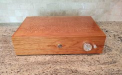
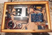
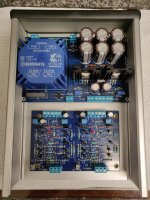
I finished up my copy of Wayne's pre burn in for about 5 hours or so to settle and gave it a listen. I had cobbled it together from spare parts that I had laying around and made a plywood box to house it. So it is a budget build. It is very detailed and dynamic, using an Aleph J paired to some 2 ways it sounded on the bright side compared to the Aikido preamp that was there. It clearly has a lower noise floor than the tubes. I then paired it with a DIY audio Sony Vfet and some horns, wow, a match made in heaven. Not bright, just right. Excellent clarity and sound stage, very transparent, really really nice sound. Thank you Wayne for making it available to us.
Attachments
This is some great sounding unit as a preamp, very impressed and many thanks are due to Wayne and Nelson and 6L6 for the effort and love to share it for all.
Is it possible to drive some sennheiser hd25 headphones with this using only the small transistors ?
( Headphones are 70ohms )
Is it possible to drive some sennheiser hd25 headphones with this using only the small transistors ?
( Headphones are 70ohms )
PJN—Looks awesome and NOT budget. Nice work. Top panel is just a drop-in friction fit? Love it. It's a great preamp! I liked reading your impressions of combos. I have a recently completed Aikido. My Wayne's pre is totally silent. Aikido does have some "hush", ear to 97db speaker cones but I'd call it quiet. These 2 preamps alone is why one needs 2 complete systems up and running to bounce around with.
You would think I would remember, but must ask a LED question. Long leg is positive and goes in round hole is what seems logical, is this right or I making stuff up again and getting away with it by sheer luck? (or look at board and figure which pad is positive.
I swear, as many of these blessed things I've installed, and I look it up everytime!
Thanks,
Russellc
I swear, as many of these blessed things I've installed, and I look it up everytime!
Thanks,
Russellc
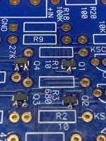
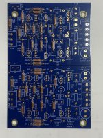
Mouser delivered my JFETS today. I'd heard that they have a habit of getting lost so I ordered twenty of them. I was thinking that this should cover any infant mortality (due to never having soldered any SMD components before) and to allow a few of them to escape in the journey between the anti-static packaging and the PCB. Holy crap those really are tiny!
I had read folks had tried a few different methods of attaching them, but what worked for me was to use a flux pen on all the PCB pads then tin them with a thin smear of solder. Next some more flux, then while holding the JFET in position with needle point tweezers apply some solder to the single leg to hold it in place. Some more flux then solder the other two legs in place before finally re-soldering the first joint. I must say it wasn't quite as bad an experience as I thought it was going to be, but glad I found my old Antex 15W iron with a tiny tip.
All in all it seemed to go fairly well. Now that my nerves have settled a bit, it's time to clean the board a bit more then continue with populating the remaining components.
Attachments
... Long leg is positive and goes in round hole is what seems logical, is this right ...
Please trace the round hole on the PCB, using your multimeter's continuity buzzer and/or ohmmeter function. To which other components is the round hole connected? Then please upload a copy of the schematic diagram where you have clearly marked the signal net of the round hole.
Please trace the round hole on the PCB, using your multimeter's continuity buzzer and/or ohmmeter function. To which other components is the round hole connected? Then please upload a copy of the schematic diagram where you have clearly marked the signal net of the round hole.
I guess it isnt a rule. Looking at post #69, where 6l6 shows the assembly pics, scroll down to the LED step...."long leg into square peg"....square it is!
whereas in teabags blog on his power supply, he states:
"The LED indication lights are present, here with a 11K resistor. The Positive Anode goes to the small round pad, the negative to the square pad". Anode is long lead...for some reason I assumed the round vs. square hole was consistent in the PCB world, oh well live and learn.
Final test will be with continuity buzzer function to double check which pad goes to positive, where long leg will go.
Russellc
Last edited:
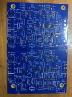
Boards are fully built, just got to drill all the necessary holes in the enclosure and wire it up. Will probably crack on with that at the weekend. 🙂
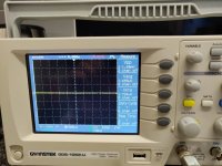
I also posted a pic of the measured ripple noise from the output after the final smoothing caps. Must say I am quite happy with that result. 🙂
I also posted a pic of the measured ripple noise from the output after the final smoothing caps. Must say I am quite happy with that result. 🙂
Attachments
Hi All
Is there a way I can vary the gain Wayne's circuit with out changing the out put impedence.
I will use this pre amp in a passive line level crossover. It comes in handy to be able to vary the gain of each channel. A pot on the end of each pre amp channel would upset the following filter. I would like to avoid the complication of adding a buffer.
The BOSOZ allows you to vary the intrinsic gain of that pre amp...I am hoping for a way to do it with Wayne's pre amp.
Thanks in advance...
PCBs are now back in stock. Apparently the warehouse has been having a very hard time getting staff in at the moment due to COVID.
If anyone is on the fence about this one... just build it. It's really good. I built it just for fun, but it has stayed in my system longer than about any other linestage I've had.
It is an excellent pairing with an M2, it just relagated an aikido that I had paired with mine to the storage closet.
Folks:
I posted a description of my new preamp on the Pass pictures thread but thought I'd leave a teaser here. The BA2018 sounds fantastic -- kudos to Mr. Colburn!
Regards,
Scott
Scott, that is a work of art. Could you provide any details on how you did it? Parts selection, etc?
It really is a paint by numbers project, build a PSU, wire the chassis inputs and outputs, stuff the board, attach it all together, adjust offset, done. 🙂
Sorry, the description in the store isn’t clear in that regard — the parts kit will stuff the stereo PCB. You’ll still need PSU, selector, volume pot, chassis, etc...
I'm pretty comfortable soldering things from a few years building Eurorack, but the move to amps has put me in a whole new world... the hard part is figuring out all the info which is so obvious to experienced people that no one needs to talk about it.
Like that you need to also build a PSU, buy a chassis, figure out some kind of volume control, ...
Painting by numbers is much easier when you know the numbers 🙂
Which is a long way of thanking you (6L6) for the guides you have provided, and respectfully asking if you have a draft version available of your upcoming build guide for the Wayne's BA 2018? I could review it for you, and it would be a great help to me.
My big open questions (not all of which can be easily answered here):
What do people recommend for a volume pot? Alps RK271 series, dual unit, audio taper, 100K? Do you need another board to solder the pot to? Or just bolt it to the chassis? link to mouser part
Rechercher des composants electroniques | Mouser Luxembourg
What about knobs? Any suppliers?
What chassis makes sense? I'm planning to run one Waynes into one Amp Camp Amp. I'd probably order the chassis from Hi-Fi 2000 (I'm EU based).
I'm looking at building a VRDN power supply, not decided yet if I'll buy an AC wall-wart or put the transformer inside the case...
The chassis panels will need some cutouts. How to design these? What i/o would one need? power, power switch, signal in/out, volume, blinky light,...???
Is it sensible to use this as both a driver for the ACA and as a headphone amp? How much complexity does this add to the output circuitry? Is it more than just a switch and a few jacks?
Last edited:
- Home
- Amplifiers
- Pass Labs
- Wayne's BA 2018 linestage