Always measure cables capacitance off circuit i.e not connected to anything else than the meter. If made one end shield connected style, use the meter on that one side. Such cables need a signal return path also so they should have two cores for hot and cold plus a shield.
Salas, just for fun I took 4 equal length hanks of different wire and tested the capacitance.
Canare L- 4ES6 shielded quad microphone cable 51.8pf
Belden RG58 50ohm RF cable 38.0pf
Belden 8641 shielded twisted pair 21.9pf
Twisted 20gauge wire 18.8pf
Seems like plain old twisted wires for internal wiring in a box should be fine?

Canare L- 4ES6 shielded quad microphone cable 51.8pf
Belden RG58 50ohm RF cable 38.0pf
Belden 8641 shielded twisted pair 21.9pf
Twisted 20gauge wire 18.8pf
Seems like plain old twisted wires for internal wiring in a box should be fine?
@longspeak
Interesting. Are those numbers per foot. It helps with other comparisons.
Thanks,
Don
Interesting. Are those numbers per foot. It helps with other comparisons.
Thanks,
Don
Seems like plain old twisted wires for internal wiring in a box should be fine?
It depends on AC magnetic fields present. Even originating from other nearby gear. If quiet enough for hum with twisted you are done. If not, you need a replacement test with coax. The input signal route to a phono is the more susceptible to interference of course, due to its very weak voltage nature.
Dear all
Being confined to a holiday-stay far away of anything resembling a soldering iron, so I have begun imagining the build... and have a question concerning the pcb-layout: how long can the connection-wires (especially the phono-input) reasonably be? I want to make my ultraFSP rather smallish (galaxy 2U 230/170 or 230/250), and therefore I’d either place the pcbs with the input/output-connectors along the chassis‘ sides, or one behind the other, both solutions resulting in wire-lengths around 150 mm...
Another, daring solution would be to stack them, but I believe this wouldn‘t fit into a 2U chassis, and it possibly would have an impact on the temp balance ... ?
Opinions, corrections please?
Thank you!
(Pic of where I cannot solder)
If its for LOMC or MC or even HMC cart the input wire length for pF is irrelevant. Due to such carts have low inductance and they won't resonate. If its for MM you want to keep pF in check. Both for the TT incoming wires capacitance vs length as long as to a lesser extent for the internal run.
If its for LOMC or MC or even HMC cart the input wire length for pF is irrelevant. Due to such carts have low inductance and they won't resonate. If its for MM you want to keep pF in check. Both for the TT incoming wires capacitance vs length as long as to a lesser extent for the internal run.
Got it, thank you!
Belden RG58 50ohm RF cable 38.0pf
40cm, I just picked a length that would aproximate what might be in an typical enclosure.
Belden says 28.5pF/ft which is 30.48cm and 40cm is 31.2% longer which makes 37.4pF so you measured it almost spot on.
https://catalog.belden.com/index.cfm?event=pd&p=PF_8240
For more complex cables conductor to conductor is another figure when conductor to shield is another figure of course.
Chassis considerations—@myleftear—You can have my Hakko station for that view right now—And we are having a serious revolution in this house at the moment with LoMC carts (DL-103, Hana ML)—playing with loading and SUTs on reg. FSP—just nuts (Much more on this later—I will be socketing one of the loading resistor spots for further experimentation)... But that is one sweet view!
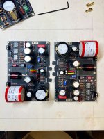
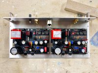
See pics. I don't see a way a square galaxy would ever work for this project—unless you wanted to get really complicated with breaking the boards apart (I did consider this for quite a while). The pencil outline on the wood is the usable space of a Galaxy 230x230mm. Also a 2U is 80mm internal height.
Second pic is what I'm doing with my personal chassis... in terms of what seems a logical layout—to me—and as small as possible due to board sizes. Height is going to be a minimum of 50mm interior height—If you want to use the sweet caps Tea includes in the BIG kit. And then just behind that limit is the CMR which is only a couple of mm shorter...So you might as well just keep options open for cap play.
Attachments
Last edited:
See pics. I don't see a way a square galaxy would ever work for this project—unless you wanted to get really complicated with breaking the boards apart (I did consider this for quite a while). The pencil outline on the wood is the usable space of a Galaxy 230x230mm.
Second pic is what I'm doing with my personal chassis... in terms of what seems a logical layout—to me—and as small as possible due to board sizes.
Hi pfarell
Awesome! Your outline made me overthink the chassis. I knew the board alone would barely fit into a 230 galaxy (4 mm too wide), and haven’t yet come to an elegant solution.
Breaking the pcb apart or cutting off 1 mm is not an option.
Neither would be to stuff them in an angled position (like a card house), just barbaric.
Using the „grooves“ would allow the bare pcb to go snugly into it but how about the populated board? even if I’d use the sides as HS.
Stacking the boards would demand a U3...
For simplicity’s sake (according to Einstein‘s simplicity law), I‘ll drop the idea of a 230.
Thank you for helping me clarifying my vague ideas!

David
A 330mm x 170mm Galaxy 2U might work. Usable interior is 310mm wide. Boards would be touching with about 4.5mm in width to spare. Similar layout like my plan with ins/outs facing back of chassis.
pfarrell:
That sounds really tight. I understand myleftear's preference, but I always err on the side of a little breathing room. Would there be space for the back panel connections?
myleftear:
Stunning photograph. If you don't mind, where is this holiday of yours?
Regards,
Scott
That sounds really tight. I understand myleftear's preference, but I always err on the side of a little breathing room. Would there be space for the back panel connections?
myleftear:
Stunning photograph. If you don't mind, where is this holiday of yours?
Regards,
Scott
plenty of depth to work with at 170mmD (my chassis has a depth of 150mm)... width would be tight—but technically doable.
Last edited:
@Salas I finally had a chance to spot check the gain at 1K Hz. I was able to adjust for 5mV in and got 502mV out of one board and 508mV out of the other board. They may come closer after allowing everything to heat up and settle more, I checked within about 5 minutes of starting up the boards. BTW, it's set for MM.
I was able to adjust for 5mV in and got 502mV out of one board and 508mV out of the other board.
That's 1.19% mV output tolerance including bench gear, great.
Thanks so much for designing this project. I can't wait to hook it to a cart and listen to it. I've been using a Hafler DH-110, this is going to run rings around that.
I think I did the math right, that would be 40dB of gain, right on the money.
Yes, and with a channels difference of merely 0.086dB. That's well matched. You are welcome.
pfarrell:
That sounds really tight. I understand myleftear's preference, but I always err on the side of a little breathing room. Would there be space for the back panel connections?
myleftear:
Stunning photograph. If you don't mind, where is this holiday of yours?
Regards,
Scott
Scott,
It’s halfway to the top of mt. Pilatus near luzern. Pretty steep, but beautiful (just like my learning curve here [emoji4])
The chassis is either 158 mm or 170 mm deep, the board is 107mm. 50 mm left for connectors...
- Home
- Source & Line
- Analogue Source
- Simplistic NJFET RIAA