Well, rats — one step forward, one step back. Suddenly when I engage S5, my bias drops to zero. The LOMC was previously working but is now kaput. Bias is normal on the other three settings but goes flat when S5 is engaged. Still reading 33mv across R2 and R3 when S5/S6 turned on. Continuity looks good. No weird flubs — switching while powered up, etc. Anything else I can measure in circuit to find what might have gone wrong?
Make sure you did not forget engaged some other switch relevant to various different gain modes. See if Q3 shows Vbe ~0.6V on the other sensitivities but not in this one. Would mean no mA left to bias it in the LoMC currents distribution balance. Your R2 R3 both give a reading shows there is bias already in the Q1 Q2 JFETs.
Try to redial T.P for LoMC mode. Does T.P wake up at all with new adjustments on both VR1? Each mode has a different bias balance. Look for intermittent joints in the involved circuit paths, including S9-S12 & R13-R16, if that approach doesn't work.
Try to redial T.P for LoMC mode. Does T.P wake up at all with new adjustments on both VR1? Each mode has a different bias balance. Look for intermittent joints in the involved circuit paths, including S9-S12 & R13-R16, if that approach doesn't work.
Phew — I think I’m just a little gun shy after the last issues. VR1 on the main board needed to be cranked up. LOMC biases fine now at 34v rails. Gain at 1K is right where it should be. Vbe almost .6v on the dot.
I think I will add a reminder line in the circuits and config post #17791. "Each sens mode has a different bias balance. Redial T.P for each".
Done it... the reminder is there.
Why now engaging LoMC by the way, you added a low output cartridge in your arsenal?
Why now engaging LoMC by the way, you added a low output cartridge in your arsenal?
Not yet — still deciding, but I wanted to check the noise — completely reasonable at 56dB. Rega recently released an Aphelion 2 as an upgrade to their flagship cart. Aphelion 1s are starting to turn up at a steep discount. I’ve never really considered Rega carts — even though my main table is a Rega Planar 8 — but the Aphelion is supposed to be excellent. Part of me would like to put all the VTA adjustment none sense with Rega tables behind me, but I’m also really interested in the Ortofon Cadenza and the Benz Micro Wood SL.
As to adjusting gain/bias settings, is there any danger in changing the gain level without making any prior adjustments to the pots? Is it important to dial everything down before powering from 63dB to 40dB, or can the adjustments be made while powered up (obviously with no music playing)? Such a jump in settings obviously results in a massive change in the bias. I just wanted to make sure nothing was in danger when changing the settings.
As to adjusting gain/bias settings, is there any danger in changing the gain level without making any prior adjustments to the pots? Is it important to dial everything down before powering from 63dB to 40dB, or can the adjustments be made while powered up (obviously with no music playing)? Such a jump in settings obviously results in a massive change in the bias. I just wanted to make sure nothing was in danger when changing the settings.
That Rega looks like an expensive amber trapped mosquito with a long nose. 🙂
There's no danger about not resetting the pots first. Just configure the DIP switches when off power.
There's no danger about not resetting the pots first. Just configure the DIP switches when off power.

The streaming DAC people gonna say we mess around with dinosaurs age tech anyway 😀
High tech and dinosaurs. The best of both worlds.😎
High tech and dinosaurs. The best of both worlds.😎
Steven Spielberg would have agreed 😉
Weird cable question.
If you make your own shielded signal cable and use the shield only as a faraday shield (one end to chassis) how do you know if you are creating a capacitance issue with the signal cable. Or, is it maybe a non issue with only one end of the shield terminated. I guess this would apply to purchased coax used the same way.
Thanks,
Don
You measure it in any configuration with an LCR meter. Even a DMM with reliable pF/nF capacitance range would do. Press REL first to zero test leads capacitance.

Success! I was able to hook everything up and get 4.0V across TP1 and TP2. I did have to lower the regulator voltage to 31.9VDC. I have it set for MM and 47k termination. I'm waiting for the rest of my pieces to come in so I can try it. I'll be pairing it with Wayne's 2018 BA linestage with a little more gain.
Since you got bench gear and you like measuring here's a test idea. Put together a 10k series 100R to GND resistors L-Pad. Send through it 500mV RMS 1kHz sinewave from your generator to the phono inputs. 5mV should reach them. To mimic MM cart level low noise signal. Compare channels output swing on your scope. To confirm gains match success. 1kHz spot check does not need an anti-RIAA input filter.
So, is it the same way/divider for for 1mV cart with 100mV signal in? Witch one UntiRIAA to buy or to build for FFT runs? I’m interested to get a shot.
Yes its general purpose 1:100 divider to bring gen noise down. Always load it with over 1k at phono input because it has 100 Ohm Zo not to lose signal. 47k all load switches off will do. Build member Bonsai's inverse RIAA proposition. Its mainly useful for response checks and squarewave checks. An Accurate Inverse RIAA Network
If you buy Hagerman's instead, its gonna do well for confirmation work but its compatible with UFSP for up to 1kHz accurate square only. Because it has an extra 50kHz constant that UFSP avoids by design choice. Last octave in frequency response test should be droopier for UFSP because of that. See #18021 #18032 #18045.
FFT 1kHz you may run already with just the divider. For best noise results shield the divider. Two small resistors fit in a connector's metal barrel.
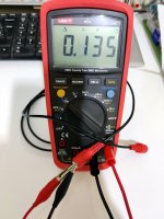
This dirt cheap 1.2m RCA interconnect cable shows 0.135nF (135pF) on an affordable DMM for instance. My calibrated LCR meter said 134.7pF at 1kHz. Pretty good agreement. Readings differ on how its laying also but +/- 10 pF.
Way cool. Thank you.
Don
- Home
- Source & Line
- Analogue Source
- Simplistic NJFET RIAA