Russellc, care to share any pics?
I am planning to use Teabags I-Select, just interested in your layout
I am planning to use Teabags I-Select, just interested in your layout
It's a great unit, just got 2 more. I have them in 3 builds.
Very simple install, just near RCA inputs. The pad is also designed to hold Alps blue, from parts Express and others. It needs an extension, be aligned with face plate hole and board needs to be at correct height for volume pot.
Power comes either from positive side of power supply, to a D/C input on board, or it has a mini power supply w/ rectifiers for small transformer and A/C input on board....your choice.. I just pirated power from positive side, I-Select draws teeny amount, negligible.
I will get a pic up when by camera.
Russellc
Last edited:
Post #932 has some pics of the select... The only thing I might try at some point is seeing if the motorized Alps would fit... you would have to deal with the connections just behind it... but you could power it and probably even a remote control board from the select... cool design.
Has anyone noticed any difference in sound between the KSC2690AYS / KSA1220AYS and the TTA004B,Q / TTC004B,Q transistors? I bought both types so want to see what people's opinions are before I build mine.
I have tried both, using 15R resistors for both sets of them. It was a while back, but I can't remember any audible differences. Neither can I remember a difference in offset stability.
I stuck with the Toshibas, because ... well, they are Toshibas 😀
I stuck with the Toshibas, because ... well, they are Toshibas 😀
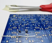
This is the best solution I've found (so far) for getting the SMD transistors soldered;
Take some masking tape and cut a very thin (1 MM or thereabouts) and long 50-75mm (2-3") strip. Put the SMD in the middle of the strip - now you have a long enough handle you can place and align it easily with two hands and then stick it down. Solder one leg. Once the first leg is done it won't move and finish the other two. Easy!
Take some masking tape and cut a very thin (1 MM or thereabouts) and long 50-75mm (2-3") strip. Put the SMD in the middle of the strip - now you have a long enough handle you can place and align it easily with two hands and then stick it down. Solder one leg. Once the first leg is done it won't move and finish the other two. Easy!
Attachments

Last edited:
inovative 🙂
though, I'm finding nothing wrong with really pointy SS tweezers
and , you can't have too much of no-need-to -wash flux
not really necessary with 3 pin critters but must have with 5 pin ones
though, I'm finding nothing wrong with really pointy SS tweezers
and , you can't have too much of no-need-to -wash flux
not really necessary with 3 pin critters but must have with 5 pin ones
This is the best solution I've found (so far) for getting the SMD transistors soldered;
Take some masking tape and cut a very thin (1 MM or thereabouts) and long 50-75mm (2-3") strip. Put the SMD in the middle of the strip - now you have a long enough handle you can place and align it easily with two hands and then stick it down. Solder one leg. Once the first leg is done it won't move and finish the other two. Easy!
I think this may work better than helping hands w/bamboo sticker! Can't wait to try!
Russellc
This is the best solution I've found (so far) for getting the SMD transistors soldered;
Take some masking tape and cut a very thin (1 MM or thereabouts) and long 50-75mm (2-3") strip. Put the SMD in the middle of the strip - now you have a long enough handle you can place and align it easily with two hands and then stick it down. Solder one leg. Once the first leg is done it won't move and finish the other two. Easy!
I could'nt be bothered to wait for my gel flux to turn up so I used some BluTack to hold mine in place while I soldered the first couple of legs, then removed the BluTack to finish them off. Turned out great!
Attachments
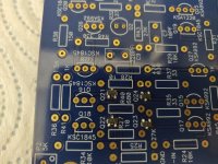
Like an idiot despite taking my time I ended up soldering the KSA1220AYS output transistors the wrong way round as I wasn't quite paying attention to the flat of the silkscreen. As a result I had a hard time desoldering one of them and it got a bit warm. Anyway I am a little concerned about the component now but I switched them round the right way regardless but have not powered up the board yet. Is there a way to test in the circuit if one of the output transistors has failed? What would I need to check or look out for? Any help would be greatly appreciated.
Okay I've sussed it. Powered it up anyway and measured and adjusted the DC offset and got it bang on zero for both channels. Next step to build it into an enclosure. I am going to use the same Hammond enclosure as I did for the Whammy. Everything will fit nice and snug. 🙂
Attachments
Parts kits are in the store now, contains all the transistors, caps and resistors to build it with the big outputs or the small. Also includes 2 extra 2SK209 in case you drop one on carpet or sneeze. 🙂 😀 
I have one built up with the kit parts, it works beautifully and is currently the preamp I listen to the most. Love it!
You can find it in the drop-down menu on the PCB page - Wayne's Burning Amp 2018 Linestage – diyAudio Store
I have one built up with the kit parts, it works beautifully and is currently the preamp I listen to the most. Love it!
You can find it in the drop-down menu on the PCB page - Wayne's Burning Amp 2018 Linestage – diyAudio Store
Last edited:
Thanks for the heads up. Got one on the way! For those wondering, yes you can get just parts kit from the store...
Russellc
Russellc
I agree with 6L6. I currently prefer my BA2018 over my other preamps.
Although I am not driving headphones, I was reading Dimitri Danyuk's "Build a Fully Balanced Transconductance Preamplifier" in this month's Audio Express. He says "I prefer the sound of transistors with large dies in circuits without overall feedback." So I thought I would replace the regular outputs I had originally installed with the optional large ones. I really can't hear much difference, so maybe that isn't critical in Wayne's circuit design. Or maybe my ears just can't hear the difference.
Although I am not driving headphones, I was reading Dimitri Danyuk's "Build a Fully Balanced Transconductance Preamplifier" in this month's Audio Express. He says "I prefer the sound of transistors with large dies in circuits without overall feedback." So I thought I would replace the regular outputs I had originally installed with the optional large ones. I really can't hear much difference, so maybe that isn't critical in Wayne's circuit design. Or maybe my ears just can't hear the difference.
Has anyone else compared boards using the "small" transistors vs the "large" ones?
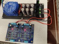
I recently rewired this preamp, reversing which side power input was with the side with input RCAs. This allowed use of one of Teabag's I-Select relay boards which have pads for Alps blue pot. One volume pot shaft extender and associated wiring later, ready to fire up.
My original build was with smaller outputs, with rewire I used another pair (older mono boards w/o mounting holes.)
This set of boards with larger outputs is more stable ( of my 2 builds ) with DC output than the smaller version. It is possible that something about the original build (bad solder on jfet?) or parts that caused this difference. One board was stable around 2-3 mv, while the other would adjust the same, it always seemed to drift up to 7-17 mv.
Sonically the large outputs seem fine. I'm letting it burn in a bit, but initially it seems a little less forgiving than the smaller outputs easier sound.
This is with it used as preamp, not as headphone amp.
Maybe just me? Both sound fine I might add.
Russellc
As a follow up, my comment on large outputs being "less forgiving" it appears that it just needed to settle in I guess, sounding fine now.
Once parts kit arrives, will assemble new board. I was going to replace the"two piece" original set of boards with this, but it's working so well I may just get another case.
Thanks 6l6 for putting this together, and to Mr Pass and Wayne for giving us this. Much appreciated
Russellc
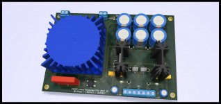
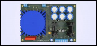
Okay a little surprise for you guys! I was looking at a power supply recently that Pete Millett built using the LM2941T and LM2991T regulators with the 5 pins and I was quite impressed how much better they were than the old 78xx and 79xx regulators. I decided it was time to build another PSU and this time I was going to make it smaller. My new design slides straight into a Hammond 1455T2201 enclosure leaving plenty of room for the BA2018 LineStage PCB. I have attached some pics for your reference. And yes there are SMD components but ones that are easy to solder by hand. 😉 Size is just 159mm x 108mm so much smaller than the last one! 🙂
Attachments
Last edited:
Hmm, the TO-220 chips are not bolted to the heatsinks, and the top side of the transformer has no markings at all. No part number, no indication of primary winding vs secondary winding, no manufacturer's logo.
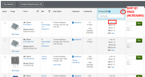
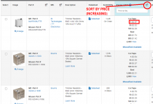
I'm surprised that you chose trimmer potentiometers in surface mount packages. At least at mouser.com, multiturn SMD trimmers are significantly more expensive than multiturn thru-hole trimmers, and the SMD units aren't any smaller.
_
I'm surprised that you chose trimmer potentiometers in surface mount packages. At least at mouser.com, multiturn SMD trimmers are significantly more expensive than multiturn thru-hole trimmers, and the SMD units aren't any smaller.
_
Attachments
- Home
- Amplifiers
- Pass Labs
- Wayne's BA 2018 linestage