Switch
Hi!
I'm having some problems understanding how to wire this push switch.
I'm using a smps with an additional 12v out that I'll use for the light. Does it matter if I connect the switch before or after the smps?
Hi!
I'm having some problems understanding how to wire this push switch.
I'm using a smps with an additional 12v out that I'll use for the light. Does it matter if I connect the switch before or after the smps?
Attachments
The switch goes before the SMPS. Do not overload the switch from SMPS current.
You can in principle connect the "lamp" (pins 4 and 5) before or after the SMPS. BUT, as the voltage before and after the SMPS is most likely different, the current in the lamp will not be the same and too much voltage (-> current) may damage the lamp. You better find a suitable voltage. 12V sounds reasonable.
You can in principle connect the "lamp" (pins 4 and 5) before or after the SMPS. BUT, as the voltage before and after the SMPS is most likely different, the current in the lamp will not be the same and too much voltage (-> current) may damage the lamp. You better find a suitable voltage. 12V sounds reasonable.
Last edited:
300w DC +-24V +-36V +-42V Dual Voltage Output + DC12V DIY HIFI Class AB power amplifier board power supply Replaces Transformer|AC/DC Adapters| - AliExpress
I'm using this one.
Is this ok?
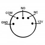
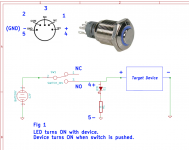
12v+ from smps to 4, 12 gnd to 5. Live to (via fuse) 2, 2 to 3, 1 to smps +in. N from Iec-socket goes straight to the smps, gnd to star grounding from smps and wall.
I'm using this one.
Is this ok?
12v+ from smps to 4, 12 gnd to 5. Live to (via fuse) 2, 2 to 3, 1 to smps +in. N from Iec-socket goes straight to the smps, gnd to star grounding from smps and wall.
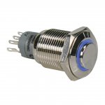
The SMPS can take up to 240Vac and pull up to 6A. As far as I can read from the photo of the switch, it can handle up to 250Vac (fine) but I cannot see the maximum switch current. Can you read that on the switch?
300w DC +-24V +-36V +-42V Dual Voltage Output + DC12V DIY HIFI Class AB power amplifier board power supply Replaces Transformer|AC/DC Adapters| - AliExpress
I'm using this one.
Is this ok?
12v+ from smps to 4, 12 gnd to 5. Live to (via fuse) 2, 2 to 3, 1 to smps +in. N from Iec-socket goes straight to the smps, gnd to star grounding from smps and wall.
12v+ from smps to 4 (OK), 12 gnd to 5 (OK). Live to (via fuse) 2 (OK), 2 to 3 (not needed), 1 to smps +in (1 or 3 can go to the input of the SMPS. The circuit sketch indicates that 3 may be a more natural choice). N from Iec-socket goes straight to the smps (OK for neutral to SMPS neutral input), gnd (safety earth I assume, NOT neutral) to star grounding from smps and wall.
Do you know how much insulation (in Volts) you have between pins 1-3 and pins 4-5?
Last edited:
Thanks man! I'll get to it!
The datasheet is just a few different wiring diagrams, showing a 12v battery as power source, no indication of insulation. But when I bought the guy specifically said it would be ok to power the led separately.
Damn... The switch is rated at 3A...
The datasheet is just a few different wiring diagrams, showing a 12v battery as power source, no indication of insulation. But when I bought the guy specifically said it would be ok to power the led separately.
Damn... The switch is rated at 3A...
Hi! The switch worked out fine, I used it in another build and it's all good.
Now getting back to the LM1875 again. Do you really need the fuses before the amp card..? I know some of you left it out, and reading about here, but It's been a while and the search function leaves me bewildered and grumpy.... 😛😛😛
Here is kinda my parts sketch from the reading of this thread. As a power supply I'll be using the same smps as Fdenys used in his build.
/Hilding
Attachments
You do not need fuses until there is a circuit problem but when there is a problem, fuses can avoid a lot of damage 😕. In other words, fuses only degrade performance (a bit) as long as they are not needed but become essential under rare circumstances (fault).
You should have at least one fuse between the supply grid (your power wall-outlet) and your amplifier unit. Standard is to put a fuse in series with the phase wire from the grid - I do so. My experience is that this fuse protects against fire, transformer damage etc. Further fuses than that cause more or less interruption in good functioning. The fuses you show indicate protection of the transformer secondary(-daries). They are likely to protect the transformer but not the amplifier if the energy in the power rail decoupling capacitors is enough to cause damage to the amplifier circuit (220uF is unrealistically little). The fuses you show are the second level of protection implemented by a careful person.
In principle, fuses should be used between the power supply output and the amplifier circuit (load) but such fuses will, if they have a value to protect, have an important negative effect on the amplifier performance and may even blow at high music levels.
In short, apart from the first (primary) fuse, further fuses are added according to your wish to protect your circuit. What I write here may not be according to rules for production of commercial amplifier circuits!
Last edited:
Hi FF!
There'll be a fuse between the wall inlet and the power switch.
So it's not save the amp if there is a surge/malfunction on the secondaries?
Then I'll probably skip them, even though I see myself as a somewhat careful person. It seems a little overprotective to have 2.5A fuses on a device that can draw 4A?
But here there's not that much capacitance either. I don't see how it would damage the supply. Normally diodes of some sort serves this purpose in amplifiers, right?
Thank you for your patient and clear answers!
Hi Vilding
if this is your first diy project its maybe better to use fuses😉.
the original kit comes by aliexpress have the fake chips and they are not able to protect itself. if you use genuine parts then its ok. they are able to survive a short cut at the output.
good luck!
chris
if this is your first diy project its maybe better to use fuses😉.
the original kit comes by aliexpress have the fake chips and they are not able to protect itself. if you use genuine parts then its ok. they are able to survive a short cut at the output.
good luck!
chris
Hi Vilding,
It is a nice combi, i am sure its sound quality and absolute silence will be a surprise to you.
When using the LM1875 supplied with the kit, i advise you to first adjust the power supply for an output voltage not exceeding about 22.5V before connecting the amplifier supply leads.
With that voltage you can expect (more than) sufficient clean output power for an average living room.
At the same time there is little risk of damaging your (fake?)chips at this voltage. But you should not short circuit the (LS)-output connections of course.
Also if you have 8 ohms power resistors available, first check the offset voltage at the output before connecting your speakers.
Finally you can measure the output power with a relatively simple multimeter and a "software generated" sine wave file, which can be downloaded from eg Johnaudiotech.
Much success and hope you will report your findings!
Chermann hehe can you tell I'm a noob..? 😛 Second attempt at amp building, and I'm bitten! So much fun both learning (though sometimes overwhelming..) and tinkering. And the reward in sound from the first amp... Wow!
I'll order all the parts fresh from Mouser. It's 45€, so it's worth it just to be assured the fault is mine and not bad parts when it goes sideways. 😀
I think I will get the complete build in at around 90€. And if it works well and sound good, it'll be a perfect gift for someone, after a few nights of listening to records through it..
I might just try it with and without fuses and see if I hear a difference.
Fdenys: I think so too! I used a similar box to yours for my first build and smps from the same seller (Folsom 7297). Looks really slick! I drilled out holes for all connections though, and had to solder them at really weird angles, which was kind of a pain, as well as measuring. Might go with something a bit easier for this one... But I really like the seamless look and will go back to it sometime, when I've figured out an easier way. But now, probably wood or... acrylic? Transparent yellow like Bonhams drums...? 🙂
And I'll absolutely report my findings!
And probably ask you guys a few million questions during the build.. 😉
Hi Vilding,
I will try to explain in brief my considerations for choosing fuse-values. Use of fuses is not an exact science.
For the first fuse connected on the primary side of the transformer, it must sustain the surge current when starting-up the power supply and of course the consumption from any intended use of the complete circuit. We like the fuse to blow in case of any circuit fault in the unit. The surge current at startup depends on the resistance of the transformer windings, the leakage inductance in the transformer, the surge characteristics of the rectifier diodes, the capacitance of the decoupling capacitors, the ESR of the decoupling capacitors, the immediate consumption at the output of the power supply (you can see it starts getting complicated) etc. In practice, you sit with the box of fuses in front of you and start with a fuse-value allowing the correct maximum power consumption of the total circuit. If the fuse blows at start-up, you try with the next higher value until the fuse does not blow. On the primary side I try to use a fast-blow (F) type. A theoretically difficult calculation but with a rather simple practical solution. Does the fuse blow in case of a circuit fault? We don’t know but the fuse value cannot be less because then it won’t start up without blowing the fuse. We can hope it will blow, depending on the fault.
For fuses on the secondary side of the transformer they must also not blow at start-up. But, at start-up the transformer is for a moment close to short-circuited and the current surge is high. It is possible to find a high value for the fuse(s) such that it will survive but hardly blow at any fault unless the fault is causing a very high failure current. Often I use slow-blow (T) fuses here. Does the secondary fuse(s) really add much protection on top of the primary fuse?
The faults we would like a fuse to protect may be delicate but not enough to blow a fuse. If one of the output transistors short to the power rail, the speaker suffers with a high DC-level but even if the DC-current is high, it will hardly blow a fuse.
Fuses do not protect against all types of circuit failure. The primary fuse serves to prevent the grid to supply energy to a circuit under destruction. For protecting speakers there are other dedicated protection circuits or integrated functions. Most failures will cause some circuit damage but it is important that fire is avoided and for that the grid is disconnected.
It seems a little overprotective to have 2.5A fuses on a device that can draw 4A? Use the fuses with the smallest value that will survive all kind of normal (intended) use.
But here there's not that much capacitance either. I don't see how it would damage the supply. Normally diodes of some sort serves this purpose in amplifiers, right?
I lost you there. Diodes protecting the amplifier?
Last edited:
For mains side of the transformer I use slow blow and on the amp side I use fast blow. There's info on this on the ESP website as well in some of Rod's amp projects.
The toroidal transformer manufacturer will generally give you recommended fuse values for the mains side. One of my suppliers recommends these values for 230-240VAC (IIRC double these values for 110-120VAC):
20-30VA - 500mA
50-80VA - 1A
160VA - 3A
300VA - 5A
Even so, check the amp project instructions you are to build for fuse details for mains and amp side as they can be lower than that specified by the transformer manufacturer. In other words specifying lower is being more cautious.
Hey People  ,
,
since my first diy Audio Attempt (2 1/2way active with SW, the Satellites driven by three LM1875) as I expected nothing and got the best Sound I ever heard, I'm planning to rebuild my Speakers with a little (just a little, the first where made with a nearly zero Budget) better Material.
As I read, the LM1875 is still a discussed Chip and even if I have to use Fakes, I think 90% of my Chips were Fake, I'd still like to use them for my "new" Speakers.
First I'd like to change the PSU. At my 1st Attempt I used 160W, 2x 18V Toroids, which resulted in about +/ 28V. This Time I'd like to limit the Voltage to +/ 24V. So I have to build a regulated PSU which can deliver 3x +/- 24V/5A.
My Idea would be something including six LM 1084IT-ADJ, as 2x3 in a symmetric PSU with one 1084 regulated and two as "Slaves" for the little extra Current. Just one Toroid, just one Rectifier. What do you think? Suggestions, Schematics, PCB's?
best regards
He who still doesn't know what he is doing ...
,since my first diy Audio Attempt (2 1/2way active with SW, the Satellites driven by three LM1875) as I expected nothing and got the best Sound I ever heard, I'm planning to rebuild my Speakers with a little (just a little, the first where made with a nearly zero Budget) better Material.
As I read, the LM1875 is still a discussed Chip and even if I have to use Fakes, I think 90% of my Chips were Fake, I'd still like to use them for my "new" Speakers.
First I'd like to change the PSU. At my 1st Attempt I used 160W, 2x 18V Toroids, which resulted in about +/ 28V. This Time I'd like to limit the Voltage to +/ 24V. So I have to build a regulated PSU which can deliver 3x +/- 24V/5A.
My Idea would be something including six LM 1084IT-ADJ, as 2x3 in a symmetric PSU with one 1084 regulated and two as "Slaves" for the little extra Current. Just one Toroid, just one Rectifier. What do you think? Suggestions, Schematics, PCB's?
best regards
He who still doesn't know what he is doing ...
Another Question: Is it possible to use a Cap Multiplier to get rid of those 3-4 Volts? If so, how should it look?
For mains side of the transformer I use slow blow and on the amp side I use fast blow. There's info on this on the ESP website as well in some of Rod's amp projects.
The toroidal transformer manufacturer will generally give you recommended fuse values for the mains side. One of my suppliers recommends these values for 230-240VAC (IIRC double these values for 110-120VAC):
20-30VA - 500mA
50-80VA - 1A
160VA - 3A
300VA - 5A
Even so, check the amp project instructions you are to build for fuse details for mains and amp side as they can be lower than that specified by the transformer manufacturer. In other words specifying lower is being more cautious.
Thanks rabbitz, very good
Yes, every good transformer manufacturer´s datasheet gives you the primary and the secondary fuse as recommendation.
chris
Hi Clueless
Sorry but i am not familiar with the cap multiplier. or 1084regulator...sorry. but as i read the today's regulators are very good in noise at the output. the current might be a problem. maybe the LDO (low drop out) LM138 (TO-CAN housing)or 338 (TO220) regulator?
if you want to have a genuine chip and cheap then try the TDA2050V (UTC2050) at reichelt - cost is 1Eruo per chip instead of 3,2Euro. max @4R is 22,5V
chris
- Home
- Amplifiers
- Chip Amps
- eBay mono LM1875 kit