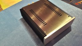
Well I guess the timing is also good to post what I think will be my final build for a LM1875 based amp.
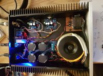
It uses a 100Va 18v-0-18v toroid, 2x ebay kits with all the BOM replaced with legit parts, I matched the values between the boards as close as possible and used Rabbitz BOM. The power supply is also from an ebay buy, the parts from Digikey. I bought the case from AliExpress, this is probably the most expensive part of this project.
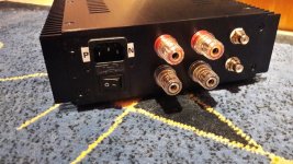
I changed the speaker protection board I had in my test setup for another, this one uses 12 to 24vac supply, the board itself hummed (the board hums, it does not come out of the speakers) when I powered it from the 18v toroid, so I put on a separate standard transformer for it that I salvaged from a wall wart (didnt want to wait weeks to get a proper transformer in this troubled times).
Grounding : the case is linked to safety earth, but the power supply board 0v isn't, this is the way I found I had 0 noise. Do you guys know if that approach is safe? I figured the whole point of the safety earth was to tie down any shorts to the case to earth, and that should be the case.
Sound is not different from my test setup, with the exception that I dont get a 60hz hum on the left channel anymore, the better layout is probably helping. I will take measurements with my scope later today and see how many watts im getting out of this kit, it is running without any significant heating at normal volumes right now.
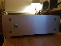
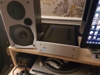
Thanks all for the help and good words, heres a few pictures of the final amplifier.
It uses a 100Va 18v-0-18v toroid, 2x ebay kits with all the BOM replaced with legit parts, I matched the values between the boards as close as possible and used Rabbitz BOM. The power supply is also from an ebay buy, the parts from Digikey. I bought the case from AliExpress, this is probably the most expensive part of this project.
I changed the speaker protection board I had in my test setup for another, this one uses 12 to 24vac supply, the board itself hummed (the board hums, it does not come out of the speakers) when I powered it from the 18v toroid, so I put on a separate standard transformer for it that I salvaged from a wall wart (didnt want to wait weeks to get a proper transformer in this troubled times).
Grounding : the case is linked to safety earth, but the power supply board 0v isn't, this is the way I found I had 0 noise. Do you guys know if that approach is safe? I figured the whole point of the safety earth was to tie down any shorts to the case to earth, and that should be the case.
Sound is not different from my test setup, with the exception that I dont get a 60hz hum on the left channel anymore, the better layout is probably helping. I will take measurements with my scope later today and see how many watts im getting out of this kit, it is running without any significant heating at normal volumes right now.
Thanks all for the help and good words, heres a few pictures of the final amplifier.
Attachments
Nice build😎..well done - congratulations.
...same housing as mine.
PSU PCB is this?:
Rectifier POWER SUPPLY PSU BOARD FOR AUDIO POWER AMPLIFIER preamp AMP DIY kit|psu board|rectifier power supply board|power amplifier board - AliExpress
chris
...same housing as mine.
PSU PCB is this?:
Rectifier POWER SUPPLY PSU BOARD FOR AUDIO POWER AMPLIFIER preamp AMP DIY kit|psu board|rectifier power supply board|power amplifier board - AliExpress
chris
Hi Chris,
Yes it looks very much the same, I got it from a different seller though.
The worst part was finding the correct connectors to fit the odd pin spacing they put on the INs/OUTS of that PCB.
Edit PCBs I got : HIFI LM3886 Power Amplifier PCB * 2pcs + Rectifier Filter Power Supply Board PCB | eBay
I didnt use the lm3886 pcbs, yet, and dont think I will since they seem to have a so-so reputation.
-Joey
Last edited:
Hi Chris,
Yes it looks very much the same, I got it from a different seller though.
The worst part was finding the correct connectors to fit the odd pin spacing they put on the INs/OUTS of that PCB.
Edit PCBs I got : HIFI LM3886 Power Amplifier PCB * 2pcs + Rectifier Filter Power Supply Board PCB | eBay
I didnt use the lm3886 pcbs, yet, and dont think I will since they seem to have a so-so reputation.
-Joey
Thanks Joey.
What is wrong with the LM3886 PCB?
I found various threads on here of people needing to do various modifications to have a properly performing unit, I didnt want to open that can of worms, for now anyway.
I also got some PCBs from that GB : Bob Cordell's Super Gain Clone PCB (LM3886) and a stripped-down version: Compact3886
So those will get used instead. Potentially in my "main system amp" project. But thats another story and I will tackle that later, with proper planning 🙂
-Joey
I also got some PCBs from that GB : Bob Cordell's Super Gain Clone PCB (LM3886) and a stripped-down version: Compact3886
So those will get used instead. Potentially in my "main system amp" project. But thats another story and I will tackle that later, with proper planning 🙂
-Joey
I found various threads on here of people needing to do various modifications to have a properly performing unit, I didnt want to open that can of worms, for now anyway.
I also got some PCBs from that GB : Bob Cordell's Super Gain Clone PCB (LM3886) and a stripped-down version: Compact3886
So those will get used instead. Potentially in my "main system amp" project. But thats another story and I will tackle that later, with proper planning 🙂
...waiting...😎
Nice build😎..well done - congratulations.
...same housing as mine.
...
chris
Do you have pictures of your current setup in that housing? Id like to compare our setups.
I know you posted them in the 'multiple 1875 high power' thread at some point but cannot find them now 😡
Do you have pictures of your current setup in that housing? Id like to compare our setups.
I know you posted them in the 'multiple 1875 high power' thread at some point but cannot find them now 😡
Hi Joey
here you are: https://www.diyaudio.com/forums/chi...ation-composite-amplifier-35.html#post6070217
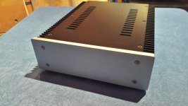
Thanks, nice work! They are some pretty handsome little enclosures, it's a shame shipping them to Canada is so expensive 🙁
Thanks, nice work! They are some pretty handsome little enclosures, it's a shame shipping them to Canada is so expensive 🙁
yep its cost over aliexpress about 30 euro but with TAX and deliver i payed 56euro. but with this cas i planned to use a "stronger" chip (3886) - as i wrote - so the heat sink and the other plates are massive cooling.
if i want to build the next amp and need a housing i will support modushop - Italy
chris
Hi
in post #618 i got after modding about -42mv and -53mV DC offset.
https://www.diyaudio.com/forums/chip-amps/341675-ebay-mono-lm1875-kit-62.html#post6138237
to trim that out i have to build a resistors network between neg and pos voltage and in the middle a potentiometer? -right? any other way to trim that out?
chris
Hi
in post #618 i got after modding about -42mv and -53mV DC offset.
https://www.diyaudio.com/forums/chip-amps/341675-ebay-mono-lm1875-kit-62.html#post6138237
to trim that out i have to build a resistors network between neg and pos voltage and in the middle a potentiometer? -right? any other way to trim that out?
chris
Hi Chris,
A generic way of doing it is as shown in the schematic. The "+ voltage" and "- voltage" should have close to the same value and preferably be stabilized voltages (regulated). You can alternatively use fixed resistors (I often do).
Attachments

You could add 2 Zener diodes of low value to stabilize the voltage, maybe 3.3 V. So you are independent of voltage fluctuation.
Maybe each with a capacitor (10-47uf 10V) in parallel. (You do not need the C over the trimmer in this version.)
The advantage, in theory, while your supply starts up, the voltage of your "trimmer" is stable at 3.3 V before the amp IC works. So you have no voltage spike at the input that could lead to negative effects.
Last edited:
You could add 2 Zener diodes of low value to stabilize the voltage, maybe 3.3 V. So you are independent of voltage fluctuation.
Maybe each with a capacitor (10-47uf 10V) in parallel. (You do not need the C over the trimmer in this version.)
The advantage, in theory, while your supply starts up, the voltage of your "trimmer" is stable at 3.3 V before the amp IC works. So you have no voltage spike at the input that could lead to negative effects.
ok Thanks to both.
Puuuuh...its a long time ago about z-Diode: 🙄😀
the Z diode is normally about 200mW, so the Iz max is I=P/Uz = 3,3/0,2 = 60mA --> Iz min is about 10% of Iz max to be in the safe side for stabilizing 3,3V. so Iz min is 6mA. so the 100k is too much for +/- 25V supply.
i calculate a current I= 25V/ 5k = 5mA
correct?
attached the schematic (please no discussion about KIcad, ....i have to use it)
chris
Attachments
No, not exactly.
You use a Zener to stabilize a voltage. Basically like this which is only the positive side. The other end of the trim pot gets the same, only negative.
Zener diodes make noise, the cap´s short the noise.
You use a Zener to stabilize a voltage. Basically like this which is only the positive side. The other end of the trim pot gets the same, only negative.
Zener diodes make noise, the cap´s short the noise.
Attachments
Last edited:
Ground the center of the 2 Zeners so one is always plus and the other is always minus. Otherwise they will "float" up and down vs. ground - ie if the positive voltage is much higher than the negative than you might not be able to get a negative voltage out at all.
Also you can use LEDs for the Zener, they work pretty well in non-critical applications.
But the best way to do this is to use a DC servo, that way the offset it automatically trimmed out continuously. The downside is that you will need another op amp for each channel. Google "audio amplifier dc servo" for lots of examples.
tommost
ok Thanks to both.
Puuuuh...its a long time ago about z-Diode: 🙄😀
the Z diode is normally about 200mW, so the Iz max is I=P/Uz = 3,3/0,2 = 60mA --> Iz min is about 10% of Iz max to be in the safe side for stabilizing 3,3V. so Iz min is 6mA. so the 100k is too much for +/- 25V supply.
i calculate a current I= 25V/ 5k = 5mA
correct?
attached the schematic (please no discussion about KIcad, ....i have to use it)
chris
The Zener got a max. load value, like 500mW. This is how much it can "burn".
So you have to choose Rs to fit two things: The current used by the following circuit, in your case the amp in and the voltage of your supply.
Don´t make that complicated, the amps input will not need that much and there is now need to let the Zener cook. Just keep your values low. A few mA will be enough.
The capacitor helps with regulation and silences the diode noise. Do not make it too large, as it has to be charged when the amp is powered up.
You can put the whole circuit on a small board and try it out.
The question is, do you really need to reduce the amps offset.
IMO it only makes sense with 100% real amp chips, as these are stable at the output and offset does not change. You do not want to adjust the offset permanently while playing music...
Then, with genuine chips, there probably will be no need to adjust offset, as it is too low anyhow.
As we say in German: "A devils circle!"
- Home
- Amplifiers
- Chip Amps
- eBay mono LM1875 kit