If such a manual offset trim gets to complicated, a DC-servo may be more elegant.
IMO it depends on the amp IC you use. Good (real) ones from the same production batch will have a very low offset and have an identical behavior, independent of temperature.
If you intend to parallel maybe three amps, you may find that they all have the same offset. One or two milli volt will not do anything bad.
With cheap China fakes anything changes, but these have to be avoided, not corrected...
Ground the center of the 2 Zeners so one is always plus and the other is always minus. Otherwise they will "float" up and down vs. ground - ie if the positive voltage is much higher than the negative than you might not be able to get a negative voltage out at all.
Thinking about this on my quarantine walk... a better way to explain this is that your circuit has zero power supply rejection at DC.
tommost
Thanks guys
i use genuine UTC2050 chip voltage is about 21,4V idle (15-0-15VAC transformer) , after load with 4R and caps at the output is was the idea to us a resistor. pages before i use a 3k3 resistor between IN+ and IN- ---> then i got at one amp -43mV the other got -53mV.
jep i forgot tho set in the middle the GND...correct.i did this schematic during a meeting today so not really 100% concentrated 😉
@ turbo
i am not understand your schematic...
chris
Chris,
You can either use a DC-servo, as suggested by Turbowatch2, or use a controlling OP-AMP (composite amplifier) to compensate the offset voltage. It is about the same effort.
You can either use a DC-servo, as suggested by Turbowatch2, or use a controlling OP-AMP (composite amplifier) to compensate the offset voltage. It is about the same effort.
Hello thread, it's me again, the noob 😉
So last night I set out to measure my amp's actual power, and I didnt take into account the fact that my rail voltages are pretty high for that chip. The transformer I got is supposed to give me 18-0-18, but it turns out it gives me 20-0-20, so I end up with about 27vdc rails after the power supply.
Last night I did the tests with a sinus wave at near clipping, 8ohms no problem, got 30.42 watts (15.6v rms)
I tried the same at 4 ohms, and while I got about 30watts too I think I triggered the current limiter multiple times, the wave kept on dropping every couple seconds and I didnt realize why for a long time.
So long story for one question, did I potentially hurt the chip doing that? I may have hit the current limiter for several minutes straight.... (yikes).
So far the amp looks like it is still working...
Hi cok666n,
I just learned from testing the genuine LM1875 that it has both current limiting and temperature protection. If you have a decent heat-sink connected to the ICs (which you have), it should not suffer damage.
I noticed the same behavior during my tests.
Very nice amplifiers you and Chris build. What was the price for the casing?
Hi Fauxfrench, thanks for the info and kind words.
The enclosure ended up costing me about 70$ (cad) total, it took over 2 months to get here, but as everything is slowed down right now that was to be expected.
The enclosure ended up costing me about 70$ (cad) total, it took over 2 months to get here, but as everything is slowed down right now that was to be expected.
yep this housing is fine, but i checked it got more expensive.
alternative with bigger fins at the heat sink,
Mini Dissipante 2U 200mm frontale 10mm NERO coperchi in alluminio 2mm e retro 3mm
...and a lot of other fine housings..🙂
chris
alternative with bigger fins at the heat sink,
Mini Dissipante 2U 200mm frontale 10mm NERO coperchi in alluminio 2mm e retro 3mm
...and a lot of other fine housings..🙂
chris
Hi Chris,
I agree with you that the modushop enclosures look great, but for a project revolving around cheap modules I felt it was overkill a bit. The modushop you linked is easily twice the price I paid for the chinese one (84euro = 130cad right now and I didnt calculate shipping).
So last night I made some maths, it seems I pushed the chip at around 2.8A current when testing the 4 ohms load. The 8ohm load had no issues at around 2A.
So I was trying to calculate wether I could use this amp on my main speakers, which are rated by the manufacturer as 6ohms (ohm meter says 3.8 ohms but Im probably missing something?)
So I figured in a worst case scenario where I would reach the same max voltage I did at 8ohms, which is unlikely. That means 15.6v into 6 ohms which would give me 2.6amps which is pretty close to what triggered the chip safety features.
By this math, do you think this chip is safe to use with 27v rails on a 6ohm speaker, considering those speakers are 91db sensivity and probably wont require a lot of power.
Edit: Food for thought... JohnAudioTech on Youtube seems to have pushed this amp in the 2.8-3.0 amps region without significant issues in his "LM1875 Ultimate Power test" video
Thanks in advance to all.
Last edited:
Hi cok666
yes this aliexpress housing is still overkill but nice and cheaper as the others.
for this small chip amp its for sure too much. if you look at rabbitz and freds build its the value of housing for this amp.
after FF hint to me if i tried a bi amping i am really thinking about that😀
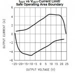
I have the same transformer with 18-0-18 and 120VA and get nearly the same voltage at idle as you wrote. 27,3V or so... i have 4x3900µF = 14000µF real per rail. during heavy bass rolls my 12" sub and W5-2143 the voltages drop to 23,4V or so. it was really loud in my 26m² room. so the PSU is not super strong. so that the "secret" if you would use a 300VA and 40000µF per rail your voltage drops not so hard and the the supply keeps about lets say 24-25 volts - thats the critical point where the lm1875 has its max current - please look at the datasheet. i attached the figure.
at the beginning of this thread i ask again FF and he takes time to explain me that. the current limiter+temperature limiter is really voltage dependent -logical - its is the chips max power (P=U*I) for that chip
if you want to measure it you have to go with your scope to the speakers terminal and check during music sessions. you will hear that 1 watt continious is not bad 😉. some impulses are higher but with a reserve of factor 20-30 its not bad.
chris
yes this aliexpress housing is still overkill but nice and cheaper as the others.
for this small chip amp its for sure too much. if you look at rabbitz and freds build its the value of housing for this amp.
after FF hint to me if i tried a bi amping i am really thinking about that😀
I have the same transformer with 18-0-18 and 120VA and get nearly the same voltage at idle as you wrote. 27,3V or so... i have 4x3900µF = 14000µF real per rail. during heavy bass rolls my 12" sub and W5-2143 the voltages drop to 23,4V or so. it was really loud in my 26m² room. so the PSU is not super strong. so that the "secret" if you would use a 300VA and 40000µF per rail your voltage drops not so hard and the the supply keeps about lets say 24-25 volts - thats the critical point where the lm1875 has its max current - please look at the datasheet. i attached the figure.
at the beginning of this thread i ask again FF and he takes time to explain me that. the current limiter+temperature limiter is really voltage dependent -logical - its is the chips max power (P=U*I) for that chip
if you want to measure it you have to go with your scope to the speakers terminal and check during music sessions. you will hear that 1 watt continious is not bad 😉. some impulses are higher but with a reserve of factor 20-30 its not bad.
chris
Attachments
Hi All,
I've two HP laptop chargers which I'm planing to power this ebay kit.
charger 1 - 18.5V 3.5A
charger 2 - 18.5V 3.5A
but there is a slight voltage difference between them when measured through DMM
in order to get the required dual rail supply, I'm planning to use this circuit from following thread (currently its inactive)
Interest in dual regulator LT1083 pcbs?
Kindly let me know is it possible to power LM1875 from this setup.
Thank you
Hi All,
I've two HP laptop chargers which I'm planing to power this ebay kit.
charger 1 - 18.5V 3.5A
charger 2 - 18.5V 3.5A
but there is a slight voltage difference between them when measured through DMM
in order to get the required dual rail supply, I'm planning to use this circuit from following thread (currently its inactive)
Interest in dual regulator LT1083 pcbs?
Kindly let me know is it possible to power LM1875 from this setup.
Thank you
A slight difference in voltage is no problem. No need for a regulated supply. Use 2200uF-4700uF between the charger outputs and the LM1875 power supply terminals (close to the board supply terminals).
NB: Make sure that charger secondary ground/return has no connection to the protective earth pin!
Last edited:
A slight difference in voltage is no problem. No need for a regulated supply. Use 2200uF-4700uF between the charger outputs and the LM1875 power supply terminals (close to the board supply terminals).
NB: Make sure that charger secondary ground/return has no connection to the protective earth pin!
Thanks for the reply
So my understanding is,
I need to connect charger outputs in series + connect capacitors in series
Connect this setup to pcb voltage input
Am I correct?
Also whats the correct way to check connection between charger secondary ground & protective earth ? Is continuity test enough?
Appreciate your help
Hi
please send us a photo of your power supplys. some charger have the output GND (minus, black, outer ring) connected to a earth contact at the wall socket plug. so that means that through the psu (charger) the earth going through. mostly the charger are not connected to mains earth. this is important to check before connecting both chargers together = in series.
and measure without connecting to the wall socket the continuity of the earth.
then connect as FF wrote
chris
Hi
please send us a photo of your power supplys. some charger have the output GND (minus, black, outer ring) connected to a earth contact at the wall socket plug. so that means that through the psu (charger) the earth going through. mostly the charger are not connected to mains earth. this is important to check before connecting both chargers together = in series.
and measure without connecting to the wall socket the continuity of the earth.
then connect as FF wrote
chris
Thanks Chris
Apologies for the delay
I've checked both chargers with multi meter
I didn't find any connection between earth pin (plug) & other pins (both side of the adapter)
Attached are pictures of two adapters
I'm trying to use this method because
1. I believe these are better build compared to other cheap power supplies
2. Its not easy to find other alternative with current lock-down situation.
Appreciate your help
Attachments
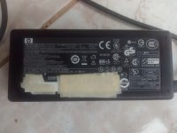
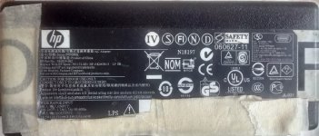
May or may not be good, as I have 2! of those that ...failed in their intended use.
Just saying 🙂
Just saying 🙂
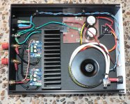
Case update
Needed a little amp to drive a small 0.1 woofer so tried my broken paper weight module (post #93) and it clapped out real fast on 4 ohm load. Looks like the fake chip was a TDA2030 as the volume was quite low before it started to crack up. So I pulled out and split my P19 LM3886 module to do the job.
This left me the Modushop Galaxy case from the P19 so installed my best LM1875 modules. Transformer oversize at 160VA and same with the heatsink but it works well, handles 4 ohm loads and sounds fine.
Attachments
- Home
- Amplifiers
- Chip Amps
- eBay mono LM1875 kit