Doesn’t seem out of line. I have 225VA for a 25 w amplifier.
dave
Even thats big Dave, why didnt you go 100va or 200va like inko suggested as that's all you need for a 100w amplifier and yours is only 25w?
Would you use less then what you have now?
Last edited:
It was not criticism or attack. I just expressed my opinion. 🙂
I completely understand your passion for DIY.
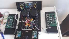
Today I received a package with PCBs.
Actually you did criticise and sort of attack and your opinion wasn't constructive. You didn't ask the right questions about the build and only made assumptions
Your built boards and design I couldve ripped into, but this is DIY audio, each to there own and to discover there own way. About time you got some proper pcbs, I'd like to see where it leads you.
Go big on the power supply 😀

Nice build Vishalk. Very tidy. I'll study that later for tricks and inspiration when I get around to a Class A amp.
Oversized power transformers make sense to me.\
50W/8 Ohms = 28.3 V peak / 3,53 Amperes peak
100W/4 Ohms = 28.3 V peak / 7,07 Amperes peak
200W/2 Ohms = 28.3 V peak / 14,14 Amperes peak
400W/1 Ohm = 28.3 V peak / 28.28 Amperes peak
800W/0.5 Ohm = 28.3 V peak / 56.57 Amperes peak
A 200VA transformer with say 25-0-25 secondaries is only going to provide around 2.6A continuous which allows 50w continuous into 8 ohm @ 2.5A.
100w into 8ohm continuous requires more like 3.5A at higher voltage.
Say 35-0-35 secondaries: 70v x 3.5 = 245VA, derate by 0.65 for rectification into a capacitive load you need 376VA to put a real 100W into 8 ohms.
Start driving 6 or 4 ohms speakers and we can see from above that the current requirements are going up quickly.
This is why the old Krell KSA50 required 2 men to lift despite being 'only 50w'. It was designed to put power into any load.
Last edited:
All right vishalk 😀 and sorry, I was wrong 😀
At first I thought it was an AB class amplifier.
I later realized it was class A, but I enjoyed teasing you
At first I thought it was an AB class amplifier.
I later realized it was class A, but I enjoyed teasing you
Hi all,
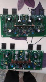
Regarding Vishalk's build and trannies. This circuit is Class A and dissipates about 80W per channel, 160 total. Rule of thumb per Linsley Hood is to derate trannie ac specs to about 65% for dc. Thus 225va would be the minimum warranted.
Next this is continuous draw. To prevent stressing the trannie to the max and it getting to hot, a margin would be prudent. Hence 300VA would be reccomendable for a stereo build as a minimum (take in to account ac line fluctuations etc).
500 VA per channel is overkill but does not hurt. The trannies will be less stressed reducing fields etc. Furthermore, the psu has some series resistance following the diodes. This somewhat reduces peak currents. This in combination with overspecced diodes will reduce stress in the diodes keeping the signal cleaner with less ringing and sidebands and emf. (not to fond of the psu cap bypasses in that aspect)
Psu capacity is large but not uncommon for a circuit like this. Hiraga specced more...
Just my 2 cents but let's take this back to the build thread. This Thread is for the nice pic's so i can get jealous. 🙂
Joris
edit: inko already replied
edit2: @vishalk, nice, you've understood why i send that tekst.
Last edited:
All right vishalk 😀 and sorry, I was wrong 😀
At first I thought it was an AB class amplifier.
I later realized it was class A, but I enjoyed teasing you
😀 it's all good hence why I said ask the right questions before you judge. I knew you were teasing, just playing along

edit: inko already replied
edit2: @vishalk, nice, you've understood why i send that tekst.
Well you taught me a great deal Joris and helped me build that monster!
Even thats big Dave, why didnt you go 100va or 200va like inko suggested as that's all you need for a 100w amplifier and yours is only 25w?
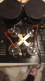
I bought 10 225VA toroids for dirt cheap (but got shipped 16). It had the right voltages, and was sitting there. The amp sounds really good.
If i had to pay real prices i might go down to 160VA, and had/habe trafos of lesser VA that i had considered using (something like 2 x 60VA IIRC), but that small only because they were on hand and cost next to nothing.
dave
Allen Wright
One of my personal guru’s. I was his Mac support guy for years (remotely). He did visit once and stayed a few days. A brilliant guy.
dave
where are the pictures? it seems you have turned this page as a discussion thread...
Post #6784
Hi Dave,
That's way over the top for the most common amplifiers. But, I get it even though I question if the power capacity will ever be even remotely approached.
-Chris
That's way over the top for the most common amplifiers. But, I get it even though I question if the power capacity will ever be even remotely approached.
-Chris
Hi Dave,
That's way over the top for the most common amplifiers. But, I get it even though I question if the power capacity will ever be even remotely approached.
Here a recent post with a very similar amplifier (except 4 channel), with 200VA per pair of amplifiers.
Chip Amp Photo Gallery
Same 18v DC rails (optimumcurrent delievery for low impedances as opposed to maximum power into 8Ω).
dave
rezabeirag, how do you think to remove heat  from your "half-kW" capable amplifier? Liquid cooling? Tons of copper? I see no space for normal heatsink.
However, impressive use of old trannies....
from your "half-kW" capable amplifier? Liquid cooling? Tons of copper? I see no space for normal heatsink.However, impressive use of old trannies....
Last edited by a moderator:
goldtune tsa
full may design full symetrical darlington vas
,super protect and super softstart , advanced grounding for zero hum.
video YouTube
full may design full symetrical darlington vas
,super protect and super softstart , advanced grounding for zero hum.
video YouTube
Attachments

Last edited:
Great looking amp dijwim. How did you finish the aluminum front panel?
It is a combination of two aluminum plates glued together. The backplate holds the screws, the fronplate (with the bended corners) is glued on the backplate.
The same is done for the top plate, so no screws are visible.
- Home
- Amplifiers
- Solid State
- Post your Solid State pics here