Let's say S=500, a box is build with a S-shape of a circle/cylinder with a diameter about 25, and another box is build with S-shape of a rectangle with 10x50.
Is the shape negligible in terms of added resonances?
Nope. And Hornresp will only model a straight unfolded enclosure. If you are very interested in understanding potential resonance issues with a fold you can calculate half and full length wavelengths to the dimensions of your fold.
Has anyone compared a built single fold TH versus a double fold TH with the exact same internal volume, throat, mouth, and driver?
Let's say S=500, a box is build with a S-shape of a circle/cylinder with a diameter about 25, and another box is build with S-shape of a rectangle with 10x50.
Is the shape negligible in terms of added resonances?
After reading Mark's response, I suspect that I may have perhaps misinterpreted the question 🙂.
Last edited:
Hornresp Update 5080-200606
Hi Everyone,
CHANGE 1
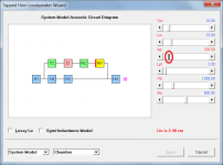
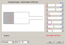
The system model acoustic circuit diagram feature, previously only included in the band pass loudspeaker wizard, has now been added to all loudspeaker wizards.
Previously when a slider control had the focus, the text in the applicable system model element box was displayed in bold font. Now the action taken is context-sensitive and depends upon the type of slider selected:
* A volume slider changes all four sides of the applicable element box to bold red, to indicate the specified volume. Attachment 1 refers.
* An area slider changes one side of the applicable element box (or boxes in the case of horn segments) to bold red, to indicate the plane of the specified cross-sectional area. Attachment 2 refers.
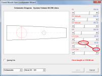
* A length slider changes one side of the applicable element box to bold red, to indicate the specified length. Attachment 3 refers.
When damping material is added to either a rear chamber, horn segment or multiple entry horn throat chamber port, the background colour of the relevant box now changes to grey. Also, radiated sound outputs are now shown as either ((( or ))) in bold pink. Attachment 4 refers.
The new system models hopefully clarify how Hornresp simulates particular designs, and how the volume, area and length parameter values are taken into account.
As mentioned in an earlier post, this change required a significant amount of work to implement. There are so many different possible combinations of model elements that I may have overlooked something. If you come across any model that does not seem correct, could you please let me know.
CHANGE 2
The operation of the length sliders in the Multiple Entry Horn Wizard has been significantly improved. Extreme values entered manually are now handled far more gracefully.
CHANGE 3
The loudspeaker wizard can now import BOXPLAN exported files specifying systems with multiple drivers.
CHANGE 4
For a closed mouth three segment OD system with an offset port, stub or passive radiator, the value of the L34 slider in the loudspeaker wizard can now be locked / fixed so that it does not change when the L23 slider is operated. This feature was requested by a user via email.
The "L34 Fixed option" can be toggled On or Off by double-clicking on the L34 slider value. Attachment 5 refers.
CHANGE 5
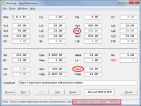
On the main input parameters window, mass is now added to a band pass system passive radiator by double-clicking on the Mmp label in edit mode, rather than by entering the value into the Mma input text box.
Mass can now also be added to the passive radiators of other systems using the same method, rather than only being able to enter the value using the loudspeaker wizard. When mass has been added, the Mmp label is shown in red
The position selected for a passive radiator in a band pass system is now indicated by PR rather than Mma, and the unused port input boxes are disabled.
Attachment 6 refers.
BUG FIX 1
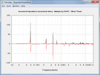
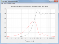
For a loudspeaker system with an offset driver and offset port, stub or passive radiator, the acoustical impedance chart plotted the load on the direct radiating side of the driver diaphragm, but wrongly indicated that it was the horn throat impedance, as shown in Attachment 7. The chart now plots the acoustical impedance at the offset throat instead, together with the correct caption, as shown in Attachment 8.
BUG FIX 2
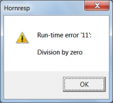
The fatal error shown in Attachment 9 would occur when trying to sample the acoustical impedance of an OD1 loudspeaker system. This bug has now been fixed.
Kind regards,
David
Hi Everyone,
CHANGE 1
The system model acoustic circuit diagram feature, previously only included in the band pass loudspeaker wizard, has now been added to all loudspeaker wizards.
Previously when a slider control had the focus, the text in the applicable system model element box was displayed in bold font. Now the action taken is context-sensitive and depends upon the type of slider selected:
* A volume slider changes all four sides of the applicable element box to bold red, to indicate the specified volume. Attachment 1 refers.
* An area slider changes one side of the applicable element box (or boxes in the case of horn segments) to bold red, to indicate the plane of the specified cross-sectional area. Attachment 2 refers.
* A length slider changes one side of the applicable element box to bold red, to indicate the specified length. Attachment 3 refers.
When damping material is added to either a rear chamber, horn segment or multiple entry horn throat chamber port, the background colour of the relevant box now changes to grey. Also, radiated sound outputs are now shown as either ((( or ))) in bold pink. Attachment 4 refers.
The new system models hopefully clarify how Hornresp simulates particular designs, and how the volume, area and length parameter values are taken into account.
As mentioned in an earlier post, this change required a significant amount of work to implement. There are so many different possible combinations of model elements that I may have overlooked something. If you come across any model that does not seem correct, could you please let me know.
CHANGE 2
The operation of the length sliders in the Multiple Entry Horn Wizard has been significantly improved. Extreme values entered manually are now handled far more gracefully.
CHANGE 3
The loudspeaker wizard can now import BOXPLAN exported files specifying systems with multiple drivers.
CHANGE 4
For a closed mouth three segment OD system with an offset port, stub or passive radiator, the value of the L34 slider in the loudspeaker wizard can now be locked / fixed so that it does not change when the L23 slider is operated. This feature was requested by a user via email.
The "L34 Fixed option" can be toggled On or Off by double-clicking on the L34 slider value. Attachment 5 refers.
CHANGE 5
On the main input parameters window, mass is now added to a band pass system passive radiator by double-clicking on the Mmp label in edit mode, rather than by entering the value into the Mma input text box.
Mass can now also be added to the passive radiators of other systems using the same method, rather than only being able to enter the value using the loudspeaker wizard. When mass has been added, the Mmp label is shown in red
The position selected for a passive radiator in a band pass system is now indicated by PR rather than Mma, and the unused port input boxes are disabled.
Attachment 6 refers.
BUG FIX 1
For a loudspeaker system with an offset driver and offset port, stub or passive radiator, the acoustical impedance chart plotted the load on the direct radiating side of the driver diaphragm, but wrongly indicated that it was the horn throat impedance, as shown in Attachment 7. The chart now plots the acoustical impedance at the offset throat instead, together with the correct caption, as shown in Attachment 8.
BUG FIX 2
The fatal error shown in Attachment 9 would occur when trying to sample the acoustical impedance of an OD1 loudspeaker system. This bug has now been fixed.
Kind regards,
David
Attachments


Pretty interesting additions David!
Thanks for all the hard work. I'm going to be checking out the diagrams.
Thanks for all the hard work. I'm going to be checking out the diagrams.
CHANGE 3
The loudspeaker wizard can now import BOXPLAN exported files specifying systems with multiple drivers.
A timely update - several of the most-recently updated BOXPLAN workbooks now support the use of dual drivers in the sim. Thanks!
Attachments
I'm going to be checking out the diagrams.
Please let me know if you find any errors.
Thanks!
Not a problem - it was "a walk in the park" compared to implementing CHANGE 1 🙂.
I'm working on understanding the acronyms. 😀Please let me know if you find any errors.
I'm working on understanding the acronyms. 😀
Hopefully the following might help a bit 🙂.
In alphabetical order:
AC = Absorber Chamber (light blue)
AP = Absorber Chamber Port (yellow)
D = Driver (light red)
H1 to H4 = Horn Segments 1 to 4 (light blue)
PR = Passive Radiator (light brown)
PT = Offset Port Tube (yellow)
RC = Rear Chamber (light green)
RP = Rear Chamber Port (yellow)
S = Stub (yellow)
TA = Throat Adaptor (yellow)
TC = Throat Chamber (light green)
TP = Throat Chamber Port (yellow)
The band pass system codes remain the same as before:
C1 to C3 = Chambers 1 to 3 (light green)
D = Driver (light red)
PR = Passive Radiator (light brown)
P1 to P3 = Ports 1 to 3 (yellow)
Sure go and take all the mystery out of it!
😀
Thanks David!
Has anyone compared a built single fold TH versus a double fold TH with the exact same internal volume, throat, mouth, and driver?
Hopefully you can translate with google. The experiment is straight, single folded and double folded transmission line boxes. Not exactly TH but very close.
HiFiForum.nu - Spelglädje under 1000 Hz
Last edited:
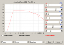
Thanks guy! Looks like 3 is the magic number. Probably explains why the the Karlson and Keystone enclosures perform so well since they are both 3 segment enclosures.
If you are very interested in understanding potential resonance issues with a fold you can calculate half and full length wavelengths to the dimensions of your fold.
I don't get this ;-) How do i calculate half/full wavelength to the dimensions?
My initial thougt about S in diffrent shapes was, that e.g. S=rectangle=10x50
will probably resonate at about 344Hz(50cm*2 wavelength), and that this diffrent to S=circle with diameter=25
Hi,
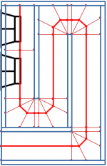
i plan to build a box in the style of the famous tabaq-mltl, but make it a 2-way system crossed-over at 500Hz with a 6db series xo, see attachments.
Above 500Hz it's a OB with a fullrange driver which should work flat down do about 120Hz.
The Woofer is a sb-acoustic sb13pfc25-8 with an series resistor at about 5ohm, which made the lower Qts possible.
While the frequency response looks very good to me, i'm not sure if the dimensions make it more a bass-reflex/helmholtz design rather than a mltl.
On diysubwoofer.org, it would probably called a slot-loaded box
The Subwoofer DIY Page - Horn Folding
If i half S and double the length, it would be much more a mltl, but i don't reach the same flat response at the low end.
Is it negligible that the throat/slot of the tabaq-design starts on the side/corner rather than in the middle like it is seen in the hornresp-schematic?
Will this box "have the sound of a mltl"?
Any comments welcome.
Johannes
Attachments
The post linked below may be of interest to some Hornresp users:
https://www.diyaudio.com/forums/ful...mulator-double-bass-reflex-2.html#post6235564
https://www.diyaudio.com/forums/ful...mulator-double-bass-reflex-2.html#post6235564
I don't get this ;-) How do i calculate half/full wavelength to the dimensions?
My initial thougt about S in diffrent shapes was, that e.g. S=rectangle=10x50
will probably resonate at about 344Hz(50cm*2 wavelength), and that this diffrent to S=circle with diameter=25
So you have applied the math and you have found a resonance. Inside of the front baffle to back resonance will bleed through your cone as well. All these things in a thoroughly designed loudspeaker have to be taken into account.
Absorbent materials are generally only effective up to a wavelength that is 4 times their depth. This has to be taken into account.
My point is that many things effect the outcome of a loudspeakers sound. Choosing which of them is the least bad is the part of the engineering that is the most difficult to choose.
Hi
I've been using Hornresp for years but trying to understand it a bit better. I assume the two design procedures 'With driver' and 'From specifications' are based on Leach's paper. These both require an estimation (or measurment) of Qmc - so what value does Hornresp use? Also been having a bit of a discussion on speakerplans forum about how to design for maximum efficiency rather than sensitivity - hope I'm onto something useful:
Hyperbolic bass horns - Speakerplans.com Forums - Page 2
Hi,
i plan to build a box in the style of the famous tabaq-mltl, but make it a 2-way system crossed-over at 500Hz with a 6db series xo, see attachments.
Above 500Hz it's a OB with a fullrange driver which should work flat down do about 120Hz.
The Woofer is a sb-acoustic sb13pfc25-8 with an series resistor at about 5ohm, which made the lower Qts possible.
While the frequency response looks very good to me, i'm not sure if the dimensions make it more a bass-reflex/helmholtz design rather than a mltl.
On diysubwoofer.org, it would probably called a slot-loaded box
The Subwoofer DIY Page - Horn Folding
If i half S and double the length, it would be much more a mltl, but i don't reach the same flat response at the low end.
Is it negligible that the throat/slot of the tabaq-design starts on the side/corner rather than in the middle like it is seen in the hornresp-schematic?
Will this box "have the sound of a mltl"?
Any comments welcome.
Johannes
Greets!
Been designing tower/column designs since the mid '60s and empirically learned that it's not a strong enough 1/4 WL resonator until it tunes a reflex/BR's alignment lower, i.e. need to shorten the vent to match it, which can sound a bit better damped, like when 'critically damping' the vent to remove any obvious 'ringing', but a true [constant taper] MLTL [by my definition] adds some obvious driver control like when a larger/longer vent is used on a BR except without the strong vent harmonics comb filtering with the driver's output [think Jensen Ultraflex/Onken 360].
In short, trading an oversize vent on a BR damped to 'taste' for a somewhat larger high aspect ratio cab with less damping + large, short vent for a net increase in efficiency/lower distortion, so by my definition many of the designs posted aren't MLTLs, but extended bass shelf alignments [EBS] in a high aspect ratio cab.
For instance, many of the MLTLs are 40-42" high after MJK's designs and once damped, quite smooth/extended, but IME it takes closer to 60" with Vas or larger net Vb to get the sort of damping/'heart attack fast' transient [horn like] response I prefer.
Many drivers today have extremely stiff suspensions [low Vas] that combined with a low Fs tuning, high power handling [Xmax] requires TL size/length vents to have a low vent mach, so better overall to morph this combo into an inverse tapered [ML] TQWT with 10:1 CR proving a good place to start simming and more often than not 'close enough', then fine tune with a vent 'stub' or learn compression horn theory if you want the best trade-off of size Vs gain BW.
Re the Tabaq, I've only looked at the original? with a really low tuning below Fs, so strictly a nearfield alignment IME and too high an aspect ratio, i.e. not enough cross sectional area [CSA] for its path-length to suit me, so based on what you've said, need to either increase it and/or add more damping to smooth it out........... or not as some of the sims I've seen look like a Rocky Mountain profile, yet folks claim a great performer, so just more proof that B0$3 was right, folks in general like their sound really 'rich' [audible harmonic distortion].
GM
Qmc - so what value does Hornresp use?
Sqrt(1 + Alpha) * Qms
- Home
- Loudspeakers
- Subwoofers
- Hornresp