Hello Prasi (and all)
Just to be sure: This would be fine in a Firstwatt-amp (F4) wouldn't it?
Apologies for this sort of questions...
david
Just to be sure: This would be fine in a Firstwatt-amp (F4) wouldn't it?
Apologies for this sort of questions...
david
Hi Leo, yes , I see your entry in the google sheet.
To; MLE,
yes, it is suitable.
regards
prasi
To; MLE,
yes, it is suitable.
regards
prasi
Hello Prasi (and all)
Just to be sure: This would be fine in a Firstwatt-amp (F4) wouldn't it?
Apologies for this sort of questions...
david
I'm using the CRC boards in two Aleph J's with great results!
I'm using the CRC boards in two Aleph J's with great results!
What capacitors are you using for Aleph J on Prasi's CRC PCB?
... and which MOSFETs?
What capacitors are you using for Aleph J on Prasi's CRC PCB?
... and which MOSFETs?
I used these caps ALC10C333EF035 | KEMET 33000μF Electrolytic Capacitor 35V dc, Snap-In - ALC10C333EF035 | RS Components
And these MOSFETS: IPP029N06NAKSA1 Infineon Technologies | Mouser United Kingdom
TBH I don't have the knowledge to choose MOSFETs but these were recommended somewhere in this thread for First Watt amps so that's what I used!
Can anyone enlighten me on what the different choice of MOSFETs would make?
Great, thanks.
You'd want the smallest possible Rds resistance, and the fastest (shortest) possible rise and fall times, so your MOSFET choice is excellent.
The Kemet caps are great as well.
You'd want the smallest possible Rds resistance, and the fastest (shortest) possible rise and fall times, so your MOSFET choice is excellent.
The Kemet caps are great as well.
Last edited:
Hello, Blitz,Just to close the loop on the CT-Discussion...I found this comment from Analog:
"but you could use the LT4320 with both windings out of phase. In this configuration, the center tap would be ground to your load while the LT4320 would have a separate local ground that would the be the "lowest" potential. These nodes are completely separated, with perhaps 10uF of biasing capacitance between them.
IN1 would connect to pin 3 on your transformer, and IN2 would connect to pin 6. The circuit would then use only two MOSFETs to rectify the positive output, these MOSFETs would connect from transformer pins 3 and 6 to OUTP. Then two diodes are connected from OUTN to each input pin to assure OUTN stays low. These diodes will not conduct the load current. The bottom gate pins are unused in this configuration. Finally, the load is connected between OUTP and the center tap."
...not sure how exactly the schematic would look like to be honest...what tyoe of diodes ? just some 1n4007 ?
LT4320 with center tapped Transformer - Q&A - Power By Linear - EngineerZone
I planned center-tapped single LT4320 configuration, but I encountered asymmetric problem.
LT4320 may not be work fine with dual rail configuration.
You should use two LT4320 with individual (separated) transformer wiring.
Edit:
Re-upload schematics.
Add last line.
Attachments

Last edited:
An update..
Till now following qty are booked
1. 49 CRC PSU PCBS,
2. 53 pairs SMD rectifier
3. 135 pairs THT rectifier
plenty to go around still..
Boards are into mfg stage and I am expecting delivery by June 2nd week.
LT4320 RECTIFIER AND LT4320 CRC PSU GROUP BUY - Google Sheets
Till now following qty are booked
1. 49 CRC PSU PCBS,
2. 53 pairs SMD rectifier
3. 135 pairs THT rectifier
plenty to go around still..
Boards are into mfg stage and I am expecting delivery by June 2nd week.
LT4320 RECTIFIER AND LT4320 CRC PSU GROUP BUY - Google Sheets

Hi Prasi
Thank you for these great concepts.
I have added myself in the google docs, how will I proceed from there?
And, for a complete PSU, I'd need (in Boards) 1 LT4320 CRC and 1 pair of either SMD LT4320 or THT LT4320
? 😕
thanks
david
Thank you for these great concepts.
I have added myself in the google docs, how will I proceed from there?
And, for a complete PSU, I'd need (in Boards) 1 LT4320 CRC and 1 pair of either SMD LT4320 or THT LT4320
? 😕
thanks
david
Hello David,
think of SMD LT4320 AND THT LT4320 as simple rectifiers. This can be used to replace your regular rectifiers in existing PSU. e.g. THT LT4320 can be used to replace https://www.vishay.com/docs/88612/gbpc12.pdf and SMD LT4320 can be used to replace https://www.mouser.in/datasheet/2/427/pb3506-1767492.pdf
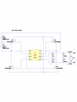
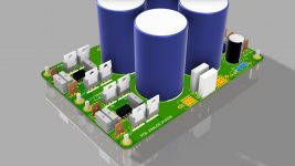
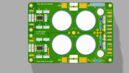
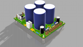
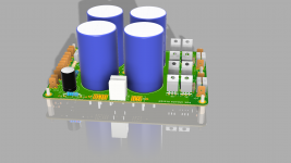
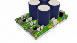
The LT4320 CRC PCB is a complete CRC PSU PCB with front end rectification by LT4320 chip.
please refer the schematic on page 1 and 3D models views attached here.
SMD LT4320 RECTIFIER 3D LT4320 based active rectifier
THT LT4320 RECTIFIER 3D LT4320 based active rectifier
think of SMD LT4320 AND THT LT4320 as simple rectifiers. This can be used to replace your regular rectifiers in existing PSU. e.g. THT LT4320 can be used to replace https://www.vishay.com/docs/88612/gbpc12.pdf and SMD LT4320 can be used to replace https://www.mouser.in/datasheet/2/427/pb3506-1767492.pdf
The LT4320 CRC PCB is a complete CRC PSU PCB with front end rectification by LT4320 chip.
please refer the schematic on page 1 and 3D models views attached here.
SMD LT4320 RECTIFIER 3D LT4320 based active rectifier
THT LT4320 RECTIFIER 3D LT4320 based active rectifier
Attachments
Last edited:

SMD LT4320 AND THT LT4320 as simple rectifiers.
The LT4320 CRC PCB is a complete CRC PSU PCB with front end rectification by LT4320 chip.
Thanks Prasi!
If I'd want to give it a shot or three, what's next? I already signed on in the google-doc GB, will you send a Paypal-request?
david
I will send you a paypal invoice once pcbs are delivered to me by june 2nd week.
meanwhile you could send me your paypal email, name and postal address via PM.
meanwhile you could send me your paypal email, name and postal address via PM.
Prasi I received your private email.
I tried to reply to thank you, but the reply email didn't work.😱
I tried to reply to thank you, but the reply email didn't work.😱
I got your PM Harry and also the details, thanks.
To all,
You can freely adjust quantities till I start invoicing/ when pcbs are delivered.. Then it becomes difficult to change and keep track. I will post here the update
regards
prasi
To all,
You can freely adjust quantities till I start invoicing/ when pcbs are delivered.. Then it becomes difficult to change and keep track. I will post here the update
regards
prasi
P16 Red CRC PSU
Hi Prasi,
I have a bunch of these CRC boards. Will they work with the LT4320 THT & smd boards from the GB's. If so, have you an image or guide as to how they would be connected.
Regards,
MM
Hi Prasi,
I have a bunch of these CRC boards. Will they work with the LT4320 THT & smd boards from the GB's. If so, have you an image or guide as to how they would be connected.
Regards,
MM
Hi Prasi,
I have a bunch of these CRC boards. Will they work with the LT4320 THT & smd boards from the GB's. If so, have you an image or guide as to how they would be connected.
Regards,
MMView attachment 849897
Yes, they will work.. please refer this image by Shaan. you need to scratch off the solder mask at marked places. You simply bypass the rectification section on your red boards , And instead use the lt4320 rectification. But remember, you need a dual secondary transformer and a pair of lt4320 rectifiers to get +/0/- supply.
CRC Power Supply (Class A amplifier)
regards
prasi
Last edited:
Hello folks,
the papal and address details of the following are not available with me. Some of you might have already participated in earlier gb, but cant find the details now. i am a really bad record keeper. pleaase share paypal and full postal address via pm.
the papal and address details of the following are not available with me. Some of you might have already participated in earlier gb, but cant find the details now. i am a really bad record keeper. pleaase share paypal and full postal address via pm.
- hifiramr
- Powersuppe
- 454Casull
- rebone
- mordikai
- danny_66
- abanico
- chiily
- sq225917
- sadface
- jason hubbard
- helmutholz
- FLAMETHROWER1
- ItsAllInMyHead
- bravi
- cal3713
- Triodes4ever
- rowli
- Analogico
Last edited:
- Home
- Group Buys
- LT4320 based active rectifier