You can modify the stuffing and the section profiles in either the input screen or the Loudspeaker Wizard under tools menu.
No I cant. I really try to follow both what you write here and tha manual. Doesnt work.
I wonder if I have some strange kind of copy of the software. Downloaded it from the hornresp homepage.
But you see what i get if i use cm in the input wizard. Totally wrong values and graphs.I can only recommend to read through the help file, all is in cm or cm2.
It actually depends what is the "rear chamber" and I currently dont understand. Neither "throat chamber".If you do not need a rear chamber, just leave zero there.
But calculated as the help text suggest (Tesla.m) it will get 0,001488. But when calculated by the software it end up in totally something else. Hard to know which is correct.And your Bl calculation is totally wrong.
Also this is intersteing, from the manual: "By default, at the common boundary between two horn segments in a multiple-segment horn the cross-sectional areas are the same for each segment. The mouth area of the first segment is equal to the throat area of the second segment. Double-clicking on any segment area label in edit mode allows different cross-sectional areas to be specified at the common boundary. The mouth area of the first segment does not necessarily have to be the same as the throat area of the second segment. This will result in a step transition at the common boundary. All horn segment area labels are shown in red when stepped segments are specified.". Doesnt work this way in the Hornresp that I got.
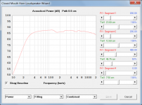
Something is terribly wrong here 🙂
Not really 🙂.
If you want to include a rear chamber, you need to specify non-zero values for both Vrc and Lrc.
If you want to include a throat chamber, you need to specify non-zero values for both Vtc and Atc.
I remember doing this with my first try and then it worked
You must have specified stepped segments - see the Help file for details (use the Find tool in the Help file to search for the keywords: stepped segments).
Doesnt work this way in the Hornresp that I got.
In Edit mode, double-click on the S1 label to activate the stepped segments mode.
All the segment area labels will change colour from black to red, to indicate that the mode has been selected.
See also the enclosed picture.
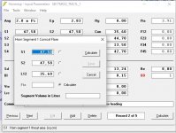
You have specified a cylindrical tube with a cross-sectional area of 47.5 square centimetres and an axial length of 35.6 centimetres. The volume of the cylinder is therefore 47.5 x 35.6 = 1691 cubic centimetres, or 1.691 litres, exactly as shown.
This is what happens if i double click.
Double-click on the S1 label to the left of the input text box, not on the text box itself.
Sorry - feel really stupid now. Naturally its 475 cm2. Its actually what i have written all over my papers.....You have specified a cylindrical tube with a cross-sectional area of 47.5 square centimetres and an axial length of 35.6 centimetres. The volume of the cylinder is therefore 47.5 x 35.6 = 1691 cubic centimetres, or 1.691 litres, exactly as shown.
But still the double click doesnt make anything else than opens the menu. Should i be in some other mode or something?
Beware - Sorry.
This should be of no problem as it is a pretty simple straight forward design. But when stumbling at the below its getting hard:
Not being able to change S2 in section 1 to another value in section 2 etc
Not being able to find the filling section
Then its not even worth going forward with positioning the driver and the port/vent.....
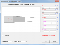
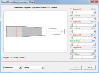
Tapered MLTL with SB17NRX2C35
Basic design
Four sections of the design:
1. Cylindrical. Start area (S1): 475 cm2, Stop area (S2): 475 cm2, Length: 35,6 cm
2. Conical. Start area (S2) 342 cm2, Stop area (S3): 228 cm2, Length: 44,7 cm
3. Cylindrical. Start area (S3): 228 cm2, Stop area (S4): 209 cm2, Length: 13,5 cm
4. Conical. Start area (S4) 209 cm2, Stop area (S5): 95 cm2, Length: 42,8 cm
Driver position 23 cm c/c from the Start/inner end (S1) of the first segment.
Port 4,5 cm dia = 15,9 cm2, Length 4 cm, placed 7,5 cm c/c from the end (S5) of the fourth segment.
Filling
Section by section:
1. Polyfiber 200 gr evenly filled
2. Polyfiber 130 gr evenly filled
3. Polyfiber 28 gr filled in the first/inner half of the section only. The second/outer half no fill.
4. No fill
Other
0,5 Ohms added in series with the driver. 14w/1m 6,5 Ohm nominal impedance.
Driver specs
Nominal Impedance 8 Ohm
DC resistance, Re 5.7 Ohm
Voice coil inductance, Le 0.15 mH
Effective piston area, Sd 118 cm2
Voice coil diameter 35.5 mm
Voice coil height 16 mm
Air gap height 5 mm
Linear coil travel (p-p) 11 mm
Magnetic flux density 0.93 T
Magnet weight 0.54 kg
Net weight 1.56 kg
Free air resonance, Fs 36.5 Hz
Sensitivity (2.83 V / 1 m) 87 dB
Mechanical Q-factor, Qms 4.55
Electrical Q-factor, Qes 0.47
Total Q-factor, Qts 0.42
Moving mass incl.air, Mms 13.9 g
Force factor, Bl 6.25 Tm
Equivalent volume, Vas 27 liters
Compliance, Cms 1.37 mm/N
Mechanical loss, Rms 0.7 kg/s
Rated power handling 50 W
Not being able to change S2 in section 1 to another value in section 2 etc
Not being able to find the filling section
Then its not even worth going forward with positioning the driver and the port/vent.....
Tapered MLTL with SB17NRX2C35
Basic design
Four sections of the design:
1. Cylindrical. Start area (S1): 475 cm2, Stop area (S2): 475 cm2, Length: 35,6 cm
2. Conical. Start area (S2) 342 cm2, Stop area (S3): 228 cm2, Length: 44,7 cm
3. Cylindrical. Start area (S3): 228 cm2, Stop area (S4): 209 cm2, Length: 13,5 cm
4. Conical. Start area (S4) 209 cm2, Stop area (S5): 95 cm2, Length: 42,8 cm
Driver position 23 cm c/c from the Start/inner end (S1) of the first segment.
Port 4,5 cm dia = 15,9 cm2, Length 4 cm, placed 7,5 cm c/c from the end (S5) of the fourth segment.
Filling
Section by section:
1. Polyfiber 200 gr evenly filled
2. Polyfiber 130 gr evenly filled
3. Polyfiber 28 gr filled in the first/inner half of the section only. The second/outer half no fill.
4. No fill
Other
0,5 Ohms added in series with the driver. 14w/1m 6,5 Ohm nominal impedance.
Driver specs
Nominal Impedance 8 Ohm
DC resistance, Re 5.7 Ohm
Voice coil inductance, Le 0.15 mH
Effective piston area, Sd 118 cm2
Voice coil diameter 35.5 mm
Voice coil height 16 mm
Air gap height 5 mm
Linear coil travel (p-p) 11 mm
Magnetic flux density 0.93 T
Magnet weight 0.54 kg
Net weight 1.56 kg
Free air resonance, Fs 36.5 Hz
Sensitivity (2.83 V / 1 m) 87 dB
Mechanical Q-factor, Qms 4.55
Electrical Q-factor, Qes 0.47
Total Q-factor, Qts 0.42
Moving mass incl.air, Mms 13.9 g
Force factor, Bl 6.25 Tm
Equivalent volume, Vas 27 liters
Compliance, Cms 1.37 mm/N
Mechanical loss, Rms 0.7 kg/s
Rated power handling 50 W
Reaized that the english is good but the actual interpretation is really bad. Clicking on the "LABEL" mean actually the S1 text and not the fillout cell.
Once again sorry, and probably the Manual makes more sense now.
Once again sorry, and probably the Manual makes more sense now.
Thanks 😊Hi Mark,
You can drive your Sd with a constant acceleration 😉
(Double click Eg twice)
Working my way through the manual and making it a MS Word file that can be found here. Adding pictures, and inserting yellow marks where explanations are needed (out of my super basic knowledge).
Ran in to the same problems that somebody else did some pages ago. Going from the input menu to the Loudspeaker Wizard the design change. All except the last of my four segments are now cylindrical. Which mean that the effect of the tapering is gone (or?). So what i basically do is that I insert filling in another design than mine - and the following graphs will show SPL etc on not my design. When I then go back to the input menu the S-values has changed.
How do I actually do to continue to design and calculate on the initially preferred input values?
How do I actually do to continue to design and calculate on the initially preferred input values?
Hornresp cannot simulate the exact design you specified, but the results will be close enough for all practical purposes if you make a few approximations as shown in the attachments. The filling material values can be adjusted to optimise the response - I have not attempted to do this.
Attachments
AGILE is the word for this software.
Realising it can do “whatever”.
Trying to follow in the app what I am reading in the manual and realise that the drop down lists change radically dependent on in what mode the app is in. This is really super great, and heavy programming, once you know every part of it. With 30+ years as a business/it project/program manager/coordinator in banking I’ve seen it before. Good craftsmanship David, and a really amazing tool. And a nightmare to write a manual for. It’s a really big effort already with a lot written in the text file.
As a newbie I sometimes have a hard time to A) Understand the “work flow” of how to design, B) Find things naturally (which is kind of natural with a complex tool), C) understand the minor tips and trix to make it work, and D) Understand what all the abbreviations stands for and what they do (which has nothing to do with the tool, but the manual).
For example, with my simple design, I run into some obstacles (except for being stupid enough to enter wrong values and not reading the help text Properly) that probably has simple solutions:
1) When I go from input parameters menu to the Loudspeaker wizard my design change and I don’t know why and how to fix it before I start to put in filling and play with the design in other ways. The same when going back to the input parameter menu.
2) Do simple things like change the position of the driver (distance from the trout (S1)) and put in a port/vent with a specific size and distance to the mouth (S5 or whatever)
3) What have I now forgot to do (work flow), what is basic/necessary and what is “bettter and better” to do
4) What is “good” (enough) and what is (too) “bad”with the result
Some of the 1-4 is general (loudspeaker design) knowledge and some is the tool. I guess it’s about what we usually say is the “user friendliness of an expert tool”.
Would someone out there part with me in a “newbiefiation” of the manual?
I know that you David already have quite a wish list of super special interesting features on your shoulders so simplifications and clarifications of for the pure app features supporting 1-4 above will have a lower prio. But “maybe in the future” there could be room for pure simple features supporting the build (maybe a developed block diagram where you can open/close ends, add/delete/move drivers, add/delete/design/redesign/move ports/vents (and other user stories/use cases)?
Hornresp cannot simulate the exact design you specified, but the results will be close enough for all practical purposes if you make a few approximations as shown in the attachments. The filling material values can be adjusted to optimise the response - I have not attempted to do this.
Thanks David
I have realised that the software always position the driver (how about multiple drivers?) at S2 and that a port/vent could be added in some way by selecting close end and put the port (hard to know which type) at the end of a segment resulting in something you designed here. As my design has a bend which is not theoretically tapered I wanted to have a separate segment for it, and ran out of segments. 🙂 Typically the type of things I talked about in my last post. 🙂
1) When I go from input parameters menu to the Loudspeaker wizard my design change
This happens with non-cylindrical stepped segment designs, for the reason given in the post linked below:
https://www.diyaudio.com/forums/subwoofers/119854-hornresp-959.html#post5810006
It's not going to change 🙂.
Hornresp cannot simulate the exact design you specified, but the results will be close enough for all practical purposes if you make a few approximations as shown in the attachments. The filling material values can be adjusted to optimise the response - I have not attempted to do this.
Then I just have to understand what other things you did to make this work than just position the Driver and the Port by using segments.
- You have other values than me for the Driver itselt. Why?
- The Re is set to 5,7 and not the Driver value...?
- I guess you selected "close end" somewhere in the design (cant remimber right now where i do that).
- You have set Rg to 0,5?
- Your menu (attached) contain Ap & Lpt, but mine Ap1 & Lp. Why (probably because set in another mode)?
Typically "work flow" topics. 🙂
2) Do simple things like change the position of the driver (distance from the trout (S1)) and put in a port/vent with a specific size and distance to the mouth (S5 or whatever)
That is all possible in the design example I posted. Set S2 and S4 to Auto, then adjust slider L12 to move the driver and L34 to move the vent.
- You have other values than me for the Driver itselt. Why?
I simply used the driver parameter values given in the specification list you posted:
https://www.diyaudio.com/forums/subwoofers/119854-hornresp-1077.html#post6219228
Rg was set to 0.5 ohms because you indicated that you wanted to include a half-ohm resistance in series with the driver.
- Home
- Loudspeakers
- Subwoofers
- Hornresp