I plan to run some tests (measurements) on a single channel first, to see how sensitive the response is to inductor positioning and spacing. I'll just wire the inductors to the existing 7th order PCB using twisted pairs. I'm also interested to discover how sensitive air-cores are to ambient fields (i.e. hum, Wi-Fi etc). Depending on the results of these experiments I may go on to wind 3 more. We shall see.....
This is a topic for ample experimentation I would say possibly of endless duration.
Don’t deprive purchasers of the DAC kit from the lust of tinkering. 🙂
George
Don’t deprive purchasers of the DAC kit from the lust of tinkering. 🙂
George
HF noise from a ladder DAC can reach 30MHz. Good luck with experiments, but I am afraid, LSB's will be lost. Building cages should be rather considered. As a bonus, it will allow a standard mounting on the PCB.As a first approach, it seems the proper orientation for limited distance btn the coils.
What is the frequency spectrum of the signal at the output of the DAC that has to be LP filtered? I would start from there.
BTW, 0.07mm wire brings memories of my first amateour radio. Do you know emanel removal method with aspirin? It helped me a lot.
Back to air-cored inductors
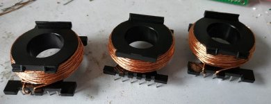
I did some researching into differing geometries of multi-layer coils and made the useful discovery that there's a kind of coil called a 'Brooks coil' based on a paper (in 1931) by a chap named Brooks. He discovered that for a given length of wire there's a maximum inductance that can be achieved - its when the height of the coil is one quarter of its width.
Therefore the coils I made before were too tall - I can get away with less wire if I create shorter, flatter coils. So that's what I did. Shorter wire means higher Q. The coils in the picture don't quite meet the Brooks criteria but they're close enough for a first attempt.
Attachments
I was a bit reluctant to mention Chapter 10 of Radiotron Designer’s Handbook on the fear that I’ll open a can of worms but I see you’ve opened it already. 😀
http://www.tubebooks.org/Books/RDH4.pdf
George
>Edit. Trying to keep it practical:
Multi layer air coil design and calculator
Optimum coil design? | Electronics Forums
http://www.tubebooks.org/Books/RDH4.pdf
George
>Edit. Trying to keep it practical:
Multi layer air coil design and calculator
Optimum coil design? | Electronics Forums
Attachments

It seems some other people are dealing with inductors meanwhile too:
Non-linearities of cored inductors
I highly recommed to follow Elvee, one of the most productive and wise members of the site.
Non-linearities of cored inductors
I highly recommed to follow Elvee, one of the most productive and wise members of the site.
If only the maximum L is the only parameter required, a Brooks coil would beat any other coil in this world. 🙂
We started in a PhiDAC with a dozen sound polluting individualy shielded SMD coils (absolutely not required when using multiple coils in series) which I objected repeatively, it is why I am not welcome anymore. Now this push for air core inductors seems lead to nowhere based on my experience.
I agree with referal to Elvee. This resource should bring back a sanity to the project that started so well with a LingDAC. A right core giving a shield with controlled air gap (for good linearity - low distortions) is a key for success.
Starting from a divaudio resource given (to which I am a third person in a row to agree) is a good start. In other words, no Brooks coils...Do you have any examples of what would constitute a good coil to use for this application?
Last edited:
Ok, cool.
But do you have a physical example of what you would use (rather than what you wouldn't use)?
Perhaps something at Mouser etc. that I could research? Something that you have perhaps already tried and had good results with?
But do you have a physical example of what you would use (rather than what you wouldn't use)?
Perhaps something at Mouser etc. that I could research? Something that you have perhaps already tried and had good results with?
Yes, it is cool... and a lot of work to do. Stop asking stupid questions. We are here to help a developer to make right decisions, saving his time on a nonsense Brooks coils.Ok, cool.
Stop asking stupid questions.
it is why I am not welcome anymore.
Honestly I can understand why now.
Anyway, how is asking for particular examples of what you deem to be superior, stupid?
I think you don't really have any alternatives to offer, which isn't particularly helpful for anyone interested in this project.
Last edited:
... it is why I am not welcome anymore.
This is, of course a falsehood. Welcome or not welcome does not apply to individuals, it applies to behaviours.
We are here to help a developer to make right decisions, saving his time on a nonsense Brooks coils.
I appreciate the irony you bring to this thread @sajunky. The air core notion came from @terranigma just as the idea of using 8 DACs instead of 1 came from you. Your idea turned out to be a valuable one, why wouldn't @terranigma's idea be worth exploring? We already know for example from the work of Bruno Putzeys that ferrite cores have certain issues - hysteresis distortion being one. I'm curious whether that issue affects the SQ in my DACs, hence @terranigma's ideas came at an opportune time.
Next stage air-cored experiments
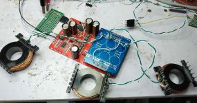
I've wired up the three 'Brooks-style' inductors that I've made so far to one of the first generation filter boards. The inductance that resulted from my single length of copper rope wasn't quite the same (about 5% lower) than the inductance of the P14s so I re-jigged the caps and termination resistance for this experiment. Seeing as I only have the 3 coils so far, I arranged the I/V converters to have twice the termination resistance (in this case, 86ohms) so that I put them in parallel, giving output to both channels.
Initial results are quite promising in that I haven't so far noticed any hum pick-up and measurements show the filter behaving as expected from simulation. When I move the coils closer I see all kinds of weird peturbations of the filter's response, quite similar to what I saw in LTspice as I varied the coil coupling coefficient. Good enough results I feel to spend another couple of hours winding three more coils and creating a second channel of filtering.
One thing that might prove more DIY friendly than ferrite cores is the predictability of the inductance of these coils - the two I created with the same target inductance turned out only to vary by less than 0.5%. If this isn't just a fluke then builders might not need an inductance meter, rather so long as they have the right wire and bobbins and can count turns precisely, they'll get close enough to the target inductance not to need to measure their creations. Let's see what happens with the next 3 coils....
Attachments
It becomes confrontational. I am sorry if you found my posting offensive, not my intend, but it is my last word. As for giving alternatives, didn't you notice it was already done?Honestly I can understand why now.
Anyway, how is asking for particular examples of what you deem to be superior, stupid?
I think you don't really have any alternatives to offer, which isn't particularly helpful for anyone interested in this project.
Yes, my bad, you are absolutely right, it is worth exploring even if the common engineering knowledge says it would need shielding to prevent degradation of DAC resolution. This is a things I said in my first response to the idea of using air coils. I wonder if you noticed that...I appreciate the irony you bring to this thread @sajunky. [...] We already know for example from the work of Bruno Putzeys that ferrite cores have certain issues - hysteresis distortion being one. I'm curious whether that issue affects the SQ in my DACs, hence @terranigma's ideas came at an opportune time.
Bruno's application is different, shielding is not needed, it would bring some negative effects like losing power efficiency. I'd like you to look at this forum resource to see whether it is good or not. It is shown in particular how to deal with hysteresis distortions (and linearity in general) in ferrite coils.
We already know for example from the work of Bruno Putzeys that ferrite cores have certain issues - hysteresis distortion being one. I'm curious whether that issue affects the SQ in my DACs, hence @terranigma's ideas came at an opportune time.
Ferrite's are useful devices, yet the issue of hysteresis, saturation and "other" distortions has always been concerning. At high frequencies I like the idea of passing signal through them into a differential input device and feeding the signal back through the ferrite to the return of the signal input. Under normal circumstances there is no net magnetic field in the core.
Is this your reference?We already know for example from the work of Bruno Putzeys that ferrite cores have certain issues
This Thing We Have About Hysteresis Distortion - PURIFI
If yes, please note that anything there is not specifically related to ferrites. It’s about magnetic hysteresis, i.e. about all ferromagnetic materials. And I wouldn’t lose my sleep over that story.
George
- Home
- Source & Line
- Digital Line Level
- lingDAC - cost effective RBCD multibit DAC design