DaveFred what slicer are you using?
Hello,
I emailed my friend who printed these for me,
"I used Simplify3D to slice the model. I thought it was by design [the grooves]. The previous one has a bigger gap than this. "
Thank you,
David.

DaveFred,
You are not the only only experiencing slits. I had the same problem with the XT25 waveguide.
Is that my design, I never did one for the XT25? Zebra analysis looks good on the SB21 model.
Last edited:
What do you guys think, zebra analysis and mesh below. Zooming in VERY closely I can see the horn take on a sort of polygonal edge that is defined be the number of "faces" I input when I make it. But the mesher and ZA still form a smooth border between the horn wall and mounting flange. Early on when people started using these some softwares didn't like seeing multiple bodies touching each other, basically each feature you see, mounting flange, horn wall, etc., were separate bodies made from separate operations. I changed so that all were joined into one big body and that solved that. Boden's may have been from that older generation unless it was downloaded from my site which are all one body models. Still looking closer at my end, but I still suspect different slicers have different methods, and some could have an issue going from the flat flange to the curved horn, perhaps separating them into different operations and so they never connect or adhere correctly. So when the product cools they separate even more?


Amazing work augerpro and all other involved 🙂 really valuable to DIY community
When going the CNC route, how do you end up with the screw holes on the back, is the piece flipped over after the waveguide has been milled?
You might ask MBrenna (sp?) in the open source speaker thread. Drilling an tapping those holes was a separate operation since a simple CNC mill can't mill that. Also it leaves open to the end user what size fastener they are using. I should just remove those holes from the .stp files.
Brandon,
did you ever do any work towards a waveguide for the DA25TX, or have any thoughts on which of the existing guides might be worth trying?
I'm going to try the SB26 guide, where the throat is a bit small, and IIRC the waveguide for the big SB/Satori tweeters, where the throat is actually a bit too big. I haven't printed one specifically for the DA25TX yet.


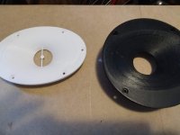
I'm looking at my model and do see a possible issue, you can sort of see it in the mesh pic above. It's directly related to what I thought I fixed for DF before, but I can see what appears to be a border or seam inside the model. Some slicers/printers are having an issue, some are not. No CNC that I've seen are having an issue. I'll work over the weekend to fix and update all the models on my site. If anyone has any other oddities in their prints that are not slicer/printer related, let me know asap.
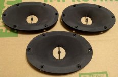
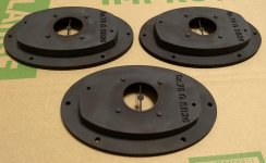
Please find attached the print i ordered online and received last week. High print quality with sanding & black paint applied in the process(cost 70€ for a pair....)
Quite impressive! Above my expectations.
Thank you! View attachment 830247
From what I see in my model, that is exactly the result I would expect. Still, I see the small crease showing up, but in my model and your result it closes up right next to the bolt hole. DF's example has the gap widest here, and this should not be happening from my model. But I suppose it is possible that the design error in that area created a condition where the horn wall didn't adhere completely to the flange, and as it cooled it pulled away, exaggerating the problem.
When going the CNC route, how do you end up with the screw holes on the back, is the piece flipped over after the waveguide has been milled?
You might ask MBrenna (sp?) in the open source speaker thread. Drilling an tapping those holes was a separate operation since a simple CNC mill can't mill that.
I don't really know how it works. I simply ordered the waveguides from an online CNC service by uploading the 3D files, and I checked a box in the order form asking if there are any threads. A few days later I got the parts with the threads in perfect condition.
I'm not sure when I will actually be able to find time to build speakers, but ordered three of the SB26G prints in MJF nylon some time back. Ordered three to get past the minimum order upcharge.
The tweeter interface and waveguide profile are serviceable, but the phase shield support is deformed on all three.
Something to consider for anyone thinking of having these printed, since the print service indicated it was entirely my fault, and won't return further emails.
Could the phase shield be made more reliable by making it more like the one on the original faceplate? My Fusion 360 skills are woefully inadequate.
Attachments
Just an update, still working the issue above. There are a couple ways to address it and I'm working out the most elegant that won't cause other unintended issues in the future. I'm also doing wavelet analysis that will be uploaded to the site too.
When you post measurement about "SB26" like in your website you refer to the "SB26 ST" or still ADC ?
Thanks
Thanks
Update: I've updated the SB21 and SB26 files to correct any hint of a problem that may cause a printing issue.
All I can think to do is make the arms thicker. From my small experience with printers it seems like very thin - especially unsupported - features can warp. Although proper slicer setup should prevent that, but I doubt commercial outfits are taking the time to do it.
I'm virtually always talking about the metal dome versions, particularly the ADC. If I talk about the the fabric STAC version I'll be clear about it being that version.
The tweeter interface and waveguide profile are serviceable, but the phase shield support is deformed on all three.
All I can think to do is make the arms thicker. From my small experience with printers it seems like very thin - especially unsupported - features can warp. Although proper slicer setup should prevent that, but I doubt commercial outfits are taking the time to do it.
When you post measurement about "SB26" like in your website you refer to the "SB26 ST" or still ADC ?
Thanks
I'm virtually always talking about the metal dome versions, particularly the ADC. If I talk about the the fabric STAC version I'll be clear about it being that version.
Hi Augerpro - just finished reading the thread. Extraordinary work you are doing here for the DIY community.
I am also interested in getting some sb26adc waveguides, but like Mandroid mentions above, I am also in agreement the phase shield should be supported at three points, not two. Like the original manufactures phase shield. This would greatly reduce the risk of warping or twisting post printing. Could adjustments be made to do this?

I am also interested in getting some sb26adc waveguides, but like Mandroid mentions above, I am also in agreement the phase shield should be supported at three points, not two. Like the original manufactures phase shield. This would greatly reduce the risk of warping or twisting post printing. Could adjustments be made to do this?
Have you used a 3D printer before? I don't believe the number of arms will make a difference, it is much more likely to do with slender objects hanging out in space. That is very tough to print correctly, and requires the operator be experienced with their slicer and printer.
Have you used a 3D printer before? I don't believe the number of arms will make a difference, it is much more likely to do with slender objects hanging out in space. That is very tough to print correctly, and requires the operator be experienced with their slicer and printer.
Exactly. I have printed this very waveguide several times with no problems - because I know how to use supports and print slowly, with a suitably sized nozzle, at a suitably low layer height. This does require my printer being in good mechanical condition and properly calibrated (esteps, extursion multiplier, etc). It does require careful support removal and a bit of filing/sanding to get the edges as clean as I'd like, but is doable.
Attachments

morbo> is there anything I can do that would help in most circumstances? Certain sizes, geometries, etc?
morbo> is there anything I can do that would help in most circumstances? Certain sizes, geometries, etc?
@Augerpro sorry I just saw this post now.
The only thing I think you could do is possibly create a model with supports included... This might save people printing the guides with suboptimal orientation (supports should be on the back, where the can't wreck surface quality of guide). I suppose you could make pre-sliced files available, but those are really only valid for one printer with one extruder/nozzle/filament combination.
I think what you are doing makes perfect sense, and is how other 3d parts are distributed. 3d printing is unfortunately still at the point where a lot of skill & knowledge are required to get good results, and a huge amount of trial and error. I got into it specifically to print your guides (though have done much more since) and have probably 200hrs of reading and tinkering to get to where I'm at now. I don't mean to discourage anyone but IME that is just the nature of the beast.
BTW I mentioned this on htguide, but will make the offer again here: if there's anything I can do to support your efforts with my printers, let me know. I think it's great what your doing and a huge contribution to the DIY audio world.
Let's say I want this waveguide CNC'ed straight into a 2 inch thick MDF/ply front.
So, no screw holes on the front. Has anyone done this before?
So, no screw holes on the front. Has anyone done this before?
Let's say I want this waveguide CNC'ed straight into a 2 inch thick MDF/ply front.
So, no screw holes on the front. Has anyone done this before?
This is ultimately what I want to try to do as well. I think what you'll have to do is extract the mesh just for the shell and start from that. I've managed to successfully machine a shell designed with ATH4 using Vectric V-Carve, so if you can do this extraction it should work similarly. Meshmixer might be able to do the extraction, but I haven't spent enough time with it. Don't forget that you'll need to machine the back side as well for proper driver mounting, so it'll be a 2-sided operation requireing you to flip the workpiece and have good alignment/calibration.
For those that have successfully printed this at home, are you printing mouth-up with supports, or mouth-down? It imports into the slicer mouth-up so I'd guess that would be the recommended strategy, but with the small alignment nubs being the only points of contact in that orientation it strikes me that getting the back flange printed properly will be tricky.
- Home
- Loudspeakers
- Multi-Way
- Open source Waveguides for CNC & 3D printing!