Bdjohns.
There is a patent that explains all about different shapes, it's out there somewhere,but can't find it again , including ear shaped design,.
Burntcoil.
There is a lot of distortions , peaks,troughs,going on in the central area of the coil area.
It's a mess basically,but strangely no one gives it a second thought?
Although the idea of the paper was to flatten the response in the 8to20k region ,the Knock on affect on the sound of the ply panel was not expected, giving me a glimpse of what I felt was missing from heavy rigid panels.
Podiums, I would think would benefit from this technique,they sounded very good but lacked that life and air that this technique brings .
I've been testing a painters picture frame similar to the panel shown on this forum but not too dissimilar to this patent w02019061685A1 on the first trials the foot came loose on the exciter ,which happens sometimes! So it's been left for some months till now.
The only trouble now is the cascamite coating ,which is thin and brittle is now cracking up!!
I was using a 1inch square piece of paper held on on one edge with masking tape ,I will take some photos when I get time,which I'm sure you will find interesting,well it was too me anyway!
Till then ,keep safe.
Steve
@Spedge
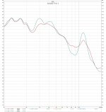
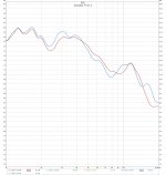
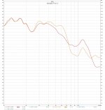
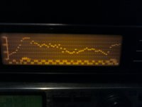
I thought you might like to see the measurements I took. Please note I have expanded the vertical axis to show 1dB steps so although the LF to HF slope looks alarming its only 10dB.
The red line is the 'natural' panel response
The paper strip was attached using sellotape and the different measurements are different positions relative to the exciters.
Cheers, Burnt
Attachments
Dave,
Looks good! CF means Carbon fiber, yes? All CF or with a light core? How are the panels supported? What exciters? Details man!
Eric
Thanks Eric. I used Carbon Fiber fabric glued to one side of heavy-duty cardboard. Then coated the CF with a two-part epoxy. The panel is sandwiched between two picture frames with foam tape around all four edges which support the panel. I used a PUI 20watt exciter mounted slightly off center on the CF side and attached to a spline.
I posted this earlier but didn't included measurements with no EQ and no sub which I finally got around to.
Thanks, Dave
Burntcoil.
Would you believe it I managed to sneak into my room🙂
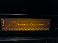
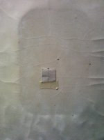
The first photo is with the mic 1in or so in front of the paper square.
The second is with the deq on peak hold and moving the mic around the edge of the square ,not over the square but over the panel.
The third is of the top edge of the ply panel in the frame.
The last deq photo is at 1m from the panel.
The other two are of the panel cracks and all, the black dot at the top of the paper is the centre of the exciter coil.
What I thought was interesting was the fact that the paper seems to be mimicking the panel response but around the the paper area seems to have a pretty flat response?
Is it acting like a phase plug?
But at the end of the day it is the sound difference that I am most interested in,you get the benefit of a light panel (paper) and a heavy panel ,you name it.
This was never ment as a permanent fix, but to find ways of curing the problems associated with this area,but it could be a permanent fix on heavy panels if needed.
I should mention that the paper should not be pressed hard up against the panel, there must be a small gap to let paper vibrate freely , hopefully without buzzing.
Different weights of paper can change things too,I did use a thinner paper ,but felt this didn't work so well?
I am desperately trying not to say anything about the the bad interference you are going to get from those two exciters in close proximity on your panel,or even on the same panel, it's bad enough using two normal tweeters that close .
Say no more.
Steve.
P S what is the response like just using one of those exciters hooked up?
Would you believe it I managed to sneak into my room🙂
The first photo is with the mic 1in or so in front of the paper square.
The second is with the deq on peak hold and moving the mic around the edge of the square ,not over the square but over the panel.
The third is of the top edge of the ply panel in the frame.
The last deq photo is at 1m from the panel.
The other two are of the panel cracks and all, the black dot at the top of the paper is the centre of the exciter coil.
What I thought was interesting was the fact that the paper seems to be mimicking the panel response but around the the paper area seems to have a pretty flat response?
Is it acting like a phase plug?
But at the end of the day it is the sound difference that I am most interested in,you get the benefit of a light panel (paper) and a heavy panel ,you name it.
This was never ment as a permanent fix, but to find ways of curing the problems associated with this area,but it could be a permanent fix on heavy panels if needed.
I should mention that the paper should not be pressed hard up against the panel, there must be a small gap to let paper vibrate freely , hopefully without buzzing.
Different weights of paper can change things too,I did use a thinner paper ,but felt this didn't work so well?
I am desperately trying not to say anything about the the bad interference you are going to get from those two exciters in close proximity on your panel,or even on the same panel, it's bad enough using two normal tweeters that close .
Say no more.
Steve.
P S what is the response like just using one of those exciters hooked up?
Attachments


Last edited:
Burntcoil.
Would you believe it I managed to sneak into my room🙂
The first photo is with the mic 1in or so in front of the paper square.
The second is with the deq on peak hold and moving the mic around the edge of the square ,not over the square but over the panel.
The third is of the top edge of the ply panel in the frame.
The last deq photo is at 1m from the panel.
The other two are of the panel cracks and all, the black dot at the top of the paper is the centre of the exciter coil.
What I thought was interesting was the fact that the paper seems to be mimicking the panel response but around the the paper area seems to have a pretty flat response?
Is it acting like a phase plug?
But at the end of the day it is the sound difference that I am most interested in, you get the benefit of a light panel (paper) and a heavy panel ,you name it.
This was never ment as a permanent fix, but to find ways of curing the problems associated with this area, but it could be a permanent fix on heavy panels if needed.
I should mention that the paper should not be pressed hard up against the panel, there must be a small gap to let paper vibrate freely , hopefully without buzzing.
Different weights of paper can change things too,I did use a thinner paper ,but felt this didn't work so well?
I am desperately trying not to say anything about the the bad interference you are going to get from those two exciters in close proximity on your panel,or even on the same panel, it's bad enough using two normal tweeters that close .
Say no more.
Steve.
P S what is the response like just using one of those exciters hooked up?
Very interesting and lots to explore. I am going to experiment more in a systematic way over the next week or two to see if I can zero in on the sort of improvement you are getting. Current theory - and as you know I have a lot of theories- is that the paper is acting kinda like a parasitic tweeter like whizzer cones. What still surprises me is just how sensitive the response is to such a small amount of material and the positional differences. The panels are far more sensitive to change that I would have expected.
On twin exciters, it's an experiment. The Tectonic exciters have a better high end response than the Daytons, the only problem being that isn't showing up in the measurements.
On the ever growing list is retesting with the Daytons, then the Tectonics and then both together so I have reference data for my file. I will share when completed as always.
On interference I have heard others talk about this and I was a single exciter advocate for a while. As two appear not to effect the subjective experience I am no longer so sure but remain open minded on the issue, its just my needle has moved a fraction. On interference, and assuming normal physics applies, the distance between centres is about 50mm which is the wavelength for 6880 hz. Any phase cancelation will occur at twice that or 13760hz so I will see if I can measure that region when I do some more testing. Yet another one for the list.
Thankyou as always for the replies and useful data, much appreciated by me.
Stay safe
Burnt
P.S. Did you get caught sneaking? I can send Bandaids?
Last edited:
My Bad!
The measurements are for the French set
.
You have a really neat room. We don't get those in the United States. Our rooms are sheetrock (drywall) with cheap mass-manufactured trim we tack to the floor corners. If we want to be really fancy we tack cheap trim to the ceiling, sometimes with a pop-up with even more tacked on cheap trim.
Kind of you to say Bradleypnw. It's the loft of an old stone house in France we had converted. The old beams are amazing, all hand cut joints and wooden pegs. You couldn't do it today it would cost a fortune. The French really knew how to throw together a house.
I have family in the Southern States and have visited Savanah. The houses there are just amazing too. Modern builds are the same all over which is a shame.
I have family in the Southern States and have visited Savanah. The houses there are just amazing too. Modern builds are the same all over which is a shame.
Burntcoil.
I would recommend that you use pink noise and your microphone to measure the response at no more than 1inch distance,and watch the wave go up and down your frequency response as you move between the outer edges of the exciter and around the whole area, wherever the two exciters radiation's meet there will be cancellations and peaks,it literally looks like a wave ,that's the best way to see how far down the response it goes in real time.
When you have two tweeters closely mounted radiating into the air you only measure the air disturbance , combing effect.
The problem is that with a panel this affect is traveling through the panel itself ,before it is even radiated into the air,which when it is ,will only compound the problem.
This is why I use only one exciter.
Steve

Hello,
Should check out this link the goldy - AER Loudspeakers They are using acrylic plate and their bbx exciter.
Cheers
Steve
Interesting that it requires a subwoofer. I'm not surprised since I think for full range DML requires low end reinforcement. I don't understand how a company can charge those prices without at the very least providing frequency response graphs!
Thanks, Dave
From AER's website about the bbx exciter: "The system operates as a pure point source and no support with subwoofers is necessary." The bass responce depends on the size and material of the panel it is attached to. They quote responce down to 28hz on large glass panels?!
The driver/exciter appears to be a largish (255gm) bass exciter (H 50 mm x W 50 mm x D 35 mm) with cone tweeter mounted into/onto its front. A step up from the aluminium drink can bottom attached to an exciter mentioned here long ago. Maybe that is where the inspiration came from?
The unit is then supposedly controlled, in realtime, by an audio processor.
I just thought that before I break up the picture panel,I might see if I can do some experiments, like adding 50x50 mix of pva to the cascamite to see if it makes it more flexible and robust, also trying some other methods to improve response?
The 1m response looks quite good but further into the room a large suck out starts to appear in the 100hz to 250hz region, normally I would bring in a LF driver to deal with this area ,and not drive the panel all the way down to 40hz ,also the panel might not have cracked up in such a bad way!
Steve
Outdoor measurements of 120x60 cm ply panel
Today I got around measuring the 4 mm thick 120x60 ply-panel with DAEX32EP. The panel is clamped at the bottom and that's it (effectively 110x60 free surface). Here is at 1 m distance on axis:

Here is response at 1 m distance (24th octave smoothing) for 0, 30, 60 and 90 degree horisontal angle:

And with psycoacoustic smoothing:

Very little output straight to the sides (90 deg), which is very obvious when you listen to the speaker.
These 6 measurements are from different parts of the panel at 0.5 m distance (center/center, top/center, center/left, center/right, top/right, top/left):

Quite uniform, the top measurements show bass output.
Then I tried slanting the clamp:

The panel now has one edge that is 80 cm and one that is 110 cm. That does look better IMO.
The results are interesting, but to me they sound like the singer is in a (wooden) box. Acoustic instruments sound fine, but they are wooden boxes, so I guess that is expected. Should I try to add more damping or a frame?
/Anton
Today I got around measuring the 4 mm thick 120x60 ply-panel with DAEX32EP. The panel is clamped at the bottom and that's it (effectively 110x60 free surface). Here is at 1 m distance on axis:
Here is response at 1 m distance (24th octave smoothing) for 0, 30, 60 and 90 degree horisontal angle:
And with psycoacoustic smoothing:
Very little output straight to the sides (90 deg), which is very obvious when you listen to the speaker.
These 6 measurements are from different parts of the panel at 0.5 m distance (center/center, top/center, center/left, center/right, top/right, top/left):
Quite uniform, the top measurements show bass output.
Then I tried slanting the clamp:
The panel now has one edge that is 80 cm and one that is 110 cm. That does look better IMO.
The results are interesting, but to me they sound like the singer is in a (wooden) box. Acoustic instruments sound fine, but they are wooden boxes, so I guess that is expected. Should I try to add more damping or a frame?
/Anton
High Speed Flash Test of sound panels
High Speed Panel Testing:
I am developing a test for measure the actual panel physical distortion that the panel to exciter has. It is based on using a high frame rate motion camera that our combustion lab has and a high speed LED flash unit that I developed for the Lab.
The LED flash generates a burst of short pulses that the duration of each pulse can be adjusted from 100 hundred nanoseconds to 10 microseconds in duration and can deliver a pulse bursts of 1 microseconds to 100 milliseconds in each burst. The LED Flash unit is sync to the High Speed Frame camera so that each Flash of LED light is captured by the camera.
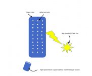
The sound board will have a matrix of small 1mm diameter retro-reflective paint spots spaced in a pre determine grid that are applied to the sound board with a cardboard mask that have the spot array cut out with a laser cutter.
There is image software that the high speed camera analysis that can map the displacement of each spot to each other to create a surface profile of the sound board distortion due to the excitation.
This can allow testing of different sound board material and different exciter placements. There are several students that want to take on this project for their student design project and putting out a paper on it . So hopefully can start when things here open up and start getting back to normal.... Here is a schematic of the concept.
Cheers,
Steve
High Speed Panel Testing:
I am developing a test for measure the actual panel physical distortion that the panel to exciter has. It is based on using a high frame rate motion camera that our combustion lab has and a high speed LED flash unit that I developed for the Lab.
The LED flash generates a burst of short pulses that the duration of each pulse can be adjusted from 100 hundred nanoseconds to 10 microseconds in duration and can deliver a pulse bursts of 1 microseconds to 100 milliseconds in each burst. The LED Flash unit is sync to the High Speed Frame camera so that each Flash of LED light is captured by the camera.
The sound board will have a matrix of small 1mm diameter retro-reflective paint spots spaced in a pre determine grid that are applied to the sound board with a cardboard mask that have the spot array cut out with a laser cutter.
There is image software that the high speed camera analysis that can map the displacement of each spot to each other to create a surface profile of the sound board distortion due to the excitation.
This can allow testing of different sound board material and different exciter placements. There are several students that want to take on this project for their student design project and putting out a paper on it . So hopefully can start when things here open up and start getting back to normal.... Here is a schematic of the concept.
Cheers,
Steve
Attachments
Good music, sounds phantastic
Hi Steve
thank you for your recording. It‘s very impressive, for me it’s the first time I‘ve listened to ‚panel sound‘ (with headphones). I hear the details perfect with a lot of air and the background sound is very clear, just behind the band like a painted curtain on stage. I wonder if the LF has in your experience more body than on the mp4 file. The saxophone especially needs more body for being comfortable.
Eric
music
these are two panels i have lying around ,not the same, thought i would record them,
your thoughts ,once again sorry for the not so good recording !
steve
Hi Steve
thank you for your recording. It‘s very impressive, for me it’s the first time I‘ve listened to ‚panel sound‘ (with headphones). I hear the details perfect with a lot of air and the background sound is very clear, just behind the band like a painted curtain on stage. I wonder if the LF has in your experience more body than on the mp4 file. The saxophone especially needs more body for being comfortable.
Eric
100ohms.
Well spotted,this was my second recording ,the first was even hotter in the mid and highs .
I was experimenting with Mike and panel positions ,the two panels were experimental ,the left was 8x12inch panel and the right was a 5inch square ,they were hanging 40inches above ground and the LF unit was about 1ft back .
The panels were pointing directly at the microphone about 18inches in front of the panels and the mic was about 30inches from each panel.
Basically I should not have turned the panels in towards the microphone,it sounded fine where I was sitting 10ft back ,but the mic was getting blasted by mid and HF, the xo to the LF was 400 , which was further away and on the floor.
Normally I'd run the LF up to 300hz and let the panels roll off somewhere below this,but I'd physically restrained the 5inch panel so that it could not go below 400hz.
The mic also rolls off sharply below 100hz,so I had to boost the LF using audacity.
I'll try and blend in the mid and bass better next time.
But it's good that you can hear and tell what is going on,the recording must be better than I thought.
Steve
Onni.
Looks like slanting the clamp has reduced the 15db peak to peak to 10db peak to peak!
And the main response is being held mainly within a 10db window,so a smoother response overall.
Your panel is also maintaining response way above 10k hooray!!
Did you try my method of pausing the music to hear if the panel makes a shoom sound after the music stops(panel keeps on resonating),this is a problem with large panels.
XO the panel around 300hz and see if it is still happening so bady,
As for damping,There are at least two thoughts on this ,my way would be to solidly clamp the panel in a heavy frame ,you would have the same sort of sound but louder ,but which would hopefully control the resonances better.
Or you could use foam to mount the panel onto a frame to dampen it,this would affect the sound , making it sound softer and smoother , like applying doping to a cone driver.
Obviously a frame would be needed for both,so you could experiment with both types,I would recommend a heavy rigid frame for both types,for less play in the frame.
Steve
Last edited:
The results are interesting, but to me they sound like the singer is in a (wooden) box. Acoustic instruments sound fine, but they are wooden boxes, so I guess that is expected. Should I try to add more damping or a frame?
/Anton
What's your panel material?
...
I was experimenting with Mike and panel positions ,the two panels were experimental ,the left was 8x12inch panel and the right was a 5inch square ,they were hanging 40inches above ground and the LF unit was about 1ft back .
The panels were pointing directly at the microphone about 18inches in front of the panels and the mic was about 30inches from each panel.
Basically I should not have turned the panels in towards the microphone,it sounded fine where I was sitting 10ft back ,but the mic was getting blasted by mid and HF, the xo to the LF was 400 , which was further away and on the floor.
Normally I'd run the LF up to 300hz and let the panels roll off somewhere below this,but I'd physically restrained the 5inch panel so that it could not go below 400hz.
The mic also rolls off sharply below 100hz,so I had to boost the LF using audacity.
I'll try and blend in the mid and bass better next time.
But it's good that you can hear and tell what is going on,the recording must be better than I thought.
Steve[/QUOTE]
Steve
Thank you for the information with the very useful details. Probably a cardioid mic will be a good choice from that far. I tried to record music of the single drivers (6/9‘) in TL/Helmholtz enclosures to show friends my newly approach with the low end. I couldn‘t do that with a omnidirectional mono- or x/y-Stereomic from 30 inches away. The sound was not as balanced as I experienced. I think the mic has to be very close or the speaker volume very high.
Eric
- Home
- Loudspeakers
- Full Range
- A Study of DMLs as a Full Range Speaker