Hi guys, I’m a new member and have been making my way through this great thread. Lots of info to get up to speed with. Many thanks to all who have contributed so far.
Decided to crack on and give it a try. Was looking at making a nomex honeycomb carbon fibre sheet, but given I have no experience with these materials and the cost is way too high if I mess it up.
As an alternative, I’ve just ordered some carbon fibre foam core panel from easycomposities. Quite a gamble to be honest as it’s still not cheap. Will let you know how I get on once it arrives and I try it out. 🙂
@Spedge
High Spedge, hope all is good with you. This is just a brief note to update you. I have been experimenting with your principle and I can confirm that it does have an effect on the higher frequencies. Early days yet, but REW is telling me the effects I have got to date are largely subtractive, but thats probably my incompetence : ) Way to early to make a judgement on that.
What I found remarkable is the degree of the effect. Barely 2 grams of paper has a distinct measurable effect and changes the profile of the frequency response. I had not realised just how sensitive the panels are to any addition, no matter how slight. Equally surprising was the effect on distortion. The strips change the distortion profile as much as they change the top end frequency response.
My guess is that there are is a sweet spot which you have hit on but I have not hit yet. Very interesting!
Best to you.
Burnt
P.S. You can tell nurse to lay off the dried frog pills, you are not going mad : )
@CovidCrazy
I‘ve thought about any less or soft material e.g. foamed rubber, felt, a.o. to make a sandwich within a stand that works like a clamb, which could be adjusted in pressure with screws/nuts. If there will be an issue, that the panel will not rest in upright position I would suggest to apply some small magnetic discs on some points on the panel and on some T-bars, which are mounted on the stand in front and back side of the panel. This will be an additional damping on some points. Instead of the magnetic discs, pieces of foam would be a little easier.
Any other ideas will be appreciated a lot
Thank you all
Eric
Last edited:
1) Addition and correction in capital letters@CovidCrazy
I‘ve thought about any less or MORE soft material e.g. foamed rubber, felt, a.o. to make a sandwich within a stand that works like a CLAMP, which could be adjusted in pressure with screws/nuts. If there will be an issue, that the panel will not rest in upright position I would suggest to apply some small magnetic discs on some points on the panel and on some T-bars, which are mounted on the stand in front and back side of the panel. This will be an additional damping on some points. Instead of the magnetic discs, pieces of foam would be a little easier.
Any other ideas will be appreciated a lot
Thank you all
Eric
2) I bear in mind the principle of cartrigde cantilevers. Most of them are pivoted, some are not like the ones of GE VR and Tannoy variluctance pickups. If you feed them with an appropriate AC, they produce some sound.
Last edited:
@Veleric
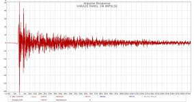
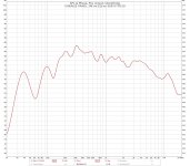
Finally got the panel measurement completed. Raw panel. Mike at 1M and aligned with exciters. I hope this is what you had in mind.
Best
Burnt
Burnt,
Thanks. Interesting. That does look like a pretty strong response at 40 Hz. I'll have to take another look at some of my ply/REW results and see if any show anything that strong near there.
Can you clarify what you mean by "raw panel"
Thanks,
Eric
Hi Eric, my pleasure
All I mean is it's a plain old panel, nothing done to it.
Burnt
Burnt,
Sorry, I wan't clearer. Is this a 12x48 ply panel? Which ply? How held? What exciter and where positioned? Probably it's one you described earlier, but I'm not sure. You've described a few, so I'm not sure which one we are talking about now.
Eric
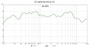
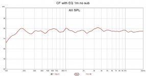
Attached are my panel measurements with no EQ and one with EQ added. The subs were turned off too. These panels are 1'x 2'.
Thanks, Dave
Looks pretty darn flat to me. They must sound great.
Looks pretty darn flat to me. They must sound great.
I think they really do sound great, especially with the subs! Of course I might be biased though and need to get other unbiased opinions.
Good evening guys,
I use a CAD drawing program at work that has modal simulation tools. I have rectangular EXP panels and have been entertaining building a pair of ear shaped panels similar to the Yamaha 6001's.
I'm hoping that the simulation tool could help design a great sounding panel, but I am limited in my understanding of how to use the tool. I have attached two simulations, one of the rectangular panel and one with the ear shape. Both are very close to 600 square inches. The material setup does not offer polystyrene, so for now I chose low density polyethylene.
What strikes me is that the ear shape has 3X the nodes of the rectangle. Is this significant? Does it mean that it would have a smoother response? I got the same result using 3/16" thick balsa. Is this tool useful to determine ideal exciter placement? What should I do next? Thanks for your help!
Attachments
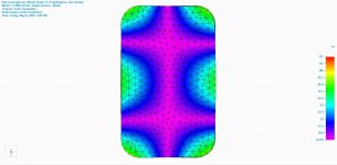
What strikes me is that the ear shape has 3X the nodes of the rectangle. Is this significant?
In this case, no. It's a bit confusing, but there are two different and completely independent meanings of the term "nodes". One meaning is the "nodes" of the modeling elements, and the other is the nodes of the vibrational shapes (modes) of the actual panel itself.
The first of these (nodes of the modeling elements) simply refers to the number of vertices of the elements (tetrahedrons in your case) into which the CAD/FEA model has divided the panel to perform the modeling calculations. Generally, more complicated shapes require finer divisions, and hence more vertices (nodes). Usually the analyst (you!) has some control over the size and hence number of elements used in a model. Using more elements (and hence nodes) provides greater accuracy, but increases the time required to run the model. In your examples, the ear shape has more of these nodes simply because more elements were used in the model. That number has everything to do with the creation of the model, and nothing to do with the performance of the panel.
The other meaning of "nodes" is this: For a given particular mode of vibration, there are some locations of a panel that move/shake a lot (antinodes) and others that don't move at all (nodes). In your plots (which represent particular modes), the fuscia (purple-ish)regions are nodes, and the bright green regions are antinodes. These are the nodes and antinodes that actually influence the performance of a panel. At least if the Azima/NXT DML concept is actually correct.
Incidentally, the number of nodes (and modes) for any panel is actually infinite. The more meaningful concept is modal "density". That is, how many modes are concentrated within the frequency range of interest.
Hope this helps at least a little.
Eric
Thanks Eric - that helps a lot. In both simulations I specified 20-16k. The number of modes was pre-selected at 4, so I left it there. Should I run it again with a tighter range of frequency but specify more modes? Will the more ideal shape generate more modes, with everything else equal?
Attached are my panel measurements with no EQ and one with EQ added. The subs were turned off too. These panels are 1'x 2'.
Thanks, Dave
Dave,
Looks good! CF means Carbon fiber, yes? All CF or with a light core? How are the panels supported? What exciters? Details man!
Eric
Burnt,
Sorry, I wan't clearer. Is this a 12x48 ply panel? Which ply? How held? What exciter and where positioned? Probably it's one you described earlier, but I'm not sure. You've described a few, so I'm not sure which one we are talking about now.
Eric
My Bad!
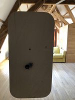
The measurements are for the French set
Poplar ply panel
600 by 1200 by 4 mm
Corner radii 140 mm
Suspended by fishing line
Exciter position 2:5th by 2:5th ratio
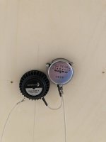
Now running twin exciters close packed
Dayton Audio DAEX32EP-4 Thruster 32mm Exciter Speaker 40W 4 Ohm and Tectonic TEAX32C30-4/B wired to give 8 ohm impedance
The REW sweep in my earlier post was 1M distance. Measurements taken were without subwoofers and the test sweep was 20-20k Hz, 10 seconds, and the graph was with 'Psy' smoothing.
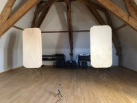
Images attached are :-
1) Panels front - N.B. Microphone position was from an earlier test.
2) Rear panel view
3) Exciters posn.
Attachments
Last edited:
- Home
- Loudspeakers
- Full Range
- A Study of DMLs as a Full Range Speaker