Anyone know where I can buy KSA1381/KSC3503 or KSA1142/KSC2682 with the same Hfe suffix? This is proving to be difficult.
Cheers
Q
Cheers
Q
Anyone know where I can buy KSA1381/KSC3503 or KSA1142/KSC2682 with the same Hfe suffix? This is proving to be difficult.
Cheers
Q
I use diffenrent rank, with no problem, since years. Unfortunately only Ebay, or Aliexpress possible, but You may get fake devices.
Sajti
I use diffenrent rank, with no problem, since years. Unfortunately only Ebay, or Aliexpress possible, but You may get fake devices.
Sajti
Thanks Sajti
I agree, If I can't get them from known suppliers I wont risk it.
Anyway I feel I will abandon the parallel VAS idea. I was originally thinking about quality high gain TO-126's in parallel, but with the advice given here and after speaking with one of my guru amp friends (g'day Hugh) I decided to re-look at it.
According to the SIM the standard VAS in this design (single or parallel) would demand a base current of around 100uA on the LTP. With the compound stage using a BC547/MJE350 & BC557/MJE340 this drops to only 4.5uA. This current does not vary much during high signal (less than 1uA) so all good in terms of linear regions. My guess is the MJE340/350 aren't super linear but the current through these doesn't change a great deal either - the hard work is done by the high gain output stage.
So the upshot is, I'm going to reverse my decision about the MJE340/350. I've been running them in all my other amps. Matched pairs of these combined with their power handling capability makes them pretty hard to beat.
Cheers
Q
Last edited:
Hi Quasi,
Try Digikey for 2SC2682, and if you only want four I can supply. I have some 2SC4793 too which are rated to 4A pulse.
Check here: Transistors - Bipolar (BJT) - Single | Discrete Semiconductor Products | DigiKey
Another option is to try using a mosfet here; VERY easy to drive!
Hugh
Try Digikey for 2SC2682, and if you only want four I can supply. I have some 2SC4793 too which are rated to 4A pulse.
Check here: Transistors - Bipolar (BJT) - Single | Discrete Semiconductor Products | DigiKey
Another option is to try using a mosfet here; VERY easy to drive!
Hugh
As you're planning to use a higher voltage for the frontend, why not use a cascode? This shifts most of the work onto the upper transistor in the cascode, which can be a small signal device. I've used the MJE340/350 well in this arrangement
It is hard to find good quality VAS transistors today. The 3503/1381 is the only high voltage, low current bjt, still in production.
2SC4793/2SA1837 still available from Unisonic, and they have small siblings from Toshiba:TTC011/TTA006.
Sajti
2SC4793/2SA1837 still available from Unisonic, and they have small siblings from Toshiba:TTC011/TTA006.
Sajti
As you're planning to use a higher voltage for the frontend, why not use a cascode? This shifts most of the work onto the upper transistor in the cascode, which can be a small signal device. I've used the MJE340/350 well in this arrangement
Hi jaycee, Simmed the cascode with a 3.3v zener so about 2 volts across the small transistor. This lowered the load on the LTP to about 55uA - pretty good, but not near the 4.5uA with the compound second stage arrangement. But for some reason I cant explain right now, the output waveform symmetry at clipping is better to just 0.02v difference vs about 0.15v!! I know it's just a SIM but wow! (not that we should care).
Cheers
Q
Hi Quasi,
Try Digikey for 2SC2682, and if you only want four I can supply. I have some 2SC4793 too which are rated to 4A pulse.
Check here: Transistors - Bipolar (BJT) - Single | Discrete Semiconductor Products | DigiKey
Another option is to try using a mosfet here; VERY easy to drive!
Hugh
Mosfet? I thought about it, worried about the input capacitance at higher frequencies. Worth a calculation though.
Cheers
Hi Hugh,
Found these. FQP3P20 & FQP3N30. Close input capacitance and RDSon. Fixable with a small cap & resistor? About a buck each from RS Components.
Found these. FQP3P20 & FQP3N30. Close input capacitance and RDSon. Fixable with a small cap & resistor? About a buck each from RS Components.
Hi Hugh,
Found these. FQP3P20 & FQP3N30. Close input capacitance and RDSon. Fixable with a small cap & resistor? About a buck each from RS Components.
Used as alternative drivers in BA-3 Front End.
Anyone know where I can buy KSA1381/KSC3503 or KSA1142/KSC2682 with the same Hfe suffix? This is proving to be difficult.
Cheers
Q
If you are beta enhancing the VAS, or cascoding it, the beta doesn’t matter that much, especially if you’re emitter degenerating it anyway. I usually use same-polarity beta enhancers. You could use rank-matched A992/ C1845 in the beta enhancer stage (ground the collector). Your method will work too, but I think your’re missing the tail resistor for the enhancer. Base current from the 1381 has nowhere to go. I’ve seen it used on the really big Crest front ends.
Quasi,
I have used a 2N7000 mosfet as the beta enhancer (source follower to drive the VAS base) with excellent results. The input capacitance of this tiny TO92 mosfet is 20pF; I can drive this with more the sufficient grunt from a 240uA collector on the LTP, that's half mA stage current! It also needs about 1V8 Vgs, and this needed a 10k collector load. No price to pay on the VAS base and output headroom either; source impedance of the mosfet is tens of ohms. With a 10k load on the LTP collector you have much, much more loop gain and this gives you much less distortion out the output due to the greater levels of feedback. The 2N7000 will soon cease production, but they are quite robust, inexpensive, and very fast. I don't suggest a mosfet as the VAS; I've had mixed results. Always better to use a bipolar, KSC3503 is good, tighter parasitics on a bipolar, and easier to titrate the correct compensation.
HD
Last edited:
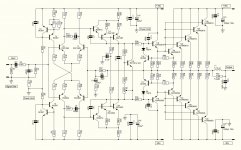
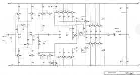
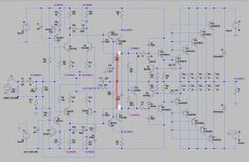
So inspired by the Krell schematic posted by Hpavictor I tried 6 x KSA992 / KSC1845 in parallel as top and bottom VAS devices, and while it simmed ok it was not as good as the compound stage. The loading on the first stage was at a minimum 40uA peaking to around 150uA at 20khz*. It was also quite asymmetrical with the lower side drawing half that - around 80uA peak.
Now most Krell ccts are more complex than mine so I'm not suggesting it's a bad idea, but just not that good in my schematic.
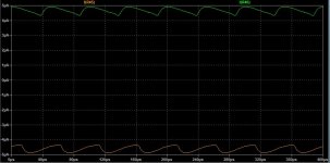
The compound stage shows very symmetrical loading on the LTP with only about 4.7uA loading (static). This rises to about 5uA peak at 20Khz but the loading symmetry is retained.
So as a result of what I found, I spent time simming some of the popular designs that load both sides of a single LTP or one side of a double LTP. The results were surprising. Some had a difference of 2 to 3 times ie: 40uA v 120uA with one design being much worse.
So does it make any difference? Who knows not me**. I would have thought though that loading on LTP tails should be the same.
Anyway this is the current drawn from the LTP's in my design at 20Khz and near full output.
Cheers
Q
*Miller capacitors removed for test.
**Line from "The Man Who Sold The World" David Bowie
Now most Krell ccts are more complex than mine so I'm not suggesting it's a bad idea, but just not that good in my schematic.
The compound stage shows very symmetrical loading on the LTP with only about 4.7uA loading (static). This rises to about 5uA peak at 20Khz but the loading symmetry is retained.
So as a result of what I found, I spent time simming some of the popular designs that load both sides of a single LTP or one side of a double LTP. The results were surprising. Some had a difference of 2 to 3 times ie: 40uA v 120uA with one design being much worse.
So does it make any difference? Who knows not me**. I would have thought though that loading on LTP tails should be the same.
Anyway this is the current drawn from the LTP's in my design at 20Khz and near full output.
Cheers
Q
*Miller capacitors removed for test.
**Line from "The Man Who Sold The World" David Bowie
Attachments
Last edited:
New Amplifier
Hello, Quasi.
I like this amplifier.
At what stage of completion is it ?.
I have a question:
The relay is I think normally closed in operation and opens in case of DC detection. It's correct ?.
1000 µF capacitors. 1,000 µf ????.
Did you open another thread?
Thank you with all my heart, Quasi.
Jacky
Hello, Quasi.
I like this amplifier.
At what stage of completion is it ?.
I have a question:
The relay is I think normally closed in operation and opens in case of DC detection. It's correct ?.
1000 µF capacitors. 1,000 µf ????.
Did you open another thread?
Thank you with all my heart, Quasi.
Jacky
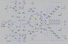
Use Miller to increase the loop gain
Distortion will decrease
Distortion will decrease
Attachments
Last edited:
Hi Jacky
The project is in progress although very slow, too slow to commit to a thread. I may start a thread when I'm about half way and post some catch-up information.
The relay in the DC protection circuit closes a few seconds after powering up and opens (releases) if a DC voltage is detected.
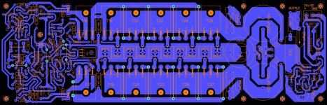
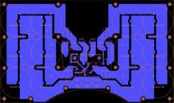
The 1,000uF capacitors on the amp PCB are bypass capacitors designed to make up for supply lead and fuse variations during higher power delivery. They could anything from about 330uF up but I chose 1,000uF. The 2 amplifiers will be driven by a complete semi-dual power supply that uses one 800VA transformer, 2 x 25amp rectifiers and 30,000uF filtering per rail. So we have one AC source to 2 DC power supplies. This almost achieves a dual mono power amplifier but not quite.
You can get an idea of the power supply from the picture. It is intended to sit close to the toroid transformer (what the curve is for).
Thank you for the interest in my project.
Cheers
Q
The project is in progress although very slow, too slow to commit to a thread. I may start a thread when I'm about half way and post some catch-up information.
The relay in the DC protection circuit closes a few seconds after powering up and opens (releases) if a DC voltage is detected.
The 1,000uF capacitors on the amp PCB are bypass capacitors designed to make up for supply lead and fuse variations during higher power delivery. They could anything from about 330uF up but I chose 1,000uF. The 2 amplifiers will be driven by a complete semi-dual power supply that uses one 800VA transformer, 2 x 25amp rectifiers and 30,000uF filtering per rail. So we have one AC source to 2 DC power supplies. This almost achieves a dual mono power amplifier but not quite.
You can get an idea of the power supply from the picture. It is intended to sit close to the toroid transformer (what the curve is for).
Thank you for the interest in my project.
Cheers
Q
Attachments
- Home
- Amplifiers
- Solid State
- Second Stage. Paralleling transistors ok?