Howdy Hugh, yes long time. Hope you are well and safe esp. with the stuff going around.
For some reason that I don't know yet, I just decided to make another amplifier. I wanted to up the ante, so after a lot of reading (and browsing the internet and my old magazines) came up with this. I tried to take learnings from Elektor, the aussie magazines, more formal publications and other sources and implement these into one design.
Sadly not a Quasi but it could be I think quite easily. I have an obsession with rail to rail output and this design achieves that with the split rails, although a quasi version probably wont quite get there.
Anyway to your points;
1. I actually intend to run a regulated supply for the +- 85v rail so the resistor instead of the CCS is an absolute option. This would be easy on the PCB as well, giving the constructor a personal choice.
2. I have the option of a cascode or equal series here. For cascode I'll probably go a BC550C/560C with something good in a TO126/TO220. I don't really want to use an MJE340/350 but there isn't a lot around with their power capability.
For series I could go with 2SA1381/2SC3503 or similar. They seem to be fast, linear with lowish Cob. Or I could go BF469/470. What's your favourite?
Great hearing from you again. Let me know your thoughts.
Cheers
Q
Hi Quasi,
why not use single 47k instead of double 22k (R5/R6)? Same idea for R28, R29, using single 100-120k. Less noise injection to the GND.
I would vote for triple darlington, and sinlgle VAS, maybe with Hawksford cascode.
Sajti
why not use single 47k instead of double 22k (R5/R6)? Same idea for R28, R29, using single 100-120k. Less noise injection to the GND.
I would vote for triple darlington, and sinlgle VAS, maybe with Hawksford cascode.
Sajti

The Sziklai draws less current from the input differential node (T5-R11, T6-R14), whereas the parallel option might draw significant current from it when beta drops.
Hi folks,
I feel I need to clarify something to avoid potential confusion. I have posted images of LT Spice screen grabs and drawings using Abacom Splan. I have drafted these separately. As far as I know there is no way to export an image from LTSpice into a different layout format.
Cheers
Q
I feel I need to clarify something to avoid potential confusion. I have posted images of LT Spice screen grabs and drawings using Abacom Splan. I have drafted these separately. As far as I know there is no way to export an image from LTSpice into a different layout format.
Cheers
Q
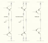
As Drawn is ok, it's a Sziklai proper.
Can also be drawn is not a Sziklai, it is not a compound anymore (no immidiate control).
Sziklai Pair are Sziklai pair, but I would recommend swapping them like As Drawn if you want amplification. It's more like an output stage on steroids.
Instead of grounding the two 56k resistors, you might consider connecting them to to opposite (better somewhat regulated) rails.
Thanks for the advice MarsBravo. I feel as though I might abandon the parallel idea and minimise the draw on the first stage.
Why is running the 56K resistors to rail better than going to ground? I thought ground would be less noisy than the rails (although I intend using regulated rails for the low current stuff.) I will also be using a separate signal ground via a 10 ohm resistor dedicated to input and feedback only.
Happy to hear another view.
Cheers
Q
Quasi,
I have played with VAS transistors for a long time and have come to a simple conclusion; use a low Cob transistor in TO126. Then choose at least a 160V transistor (I use the KSC3503 or the 2SC2682) and run them hard, around 10mA or even more. These are low Ic devices, high voltage and speed, and well sinked will run up to 8W. The low Cob minimises compensation issues. Both those transistors run max gain-bandwidth at around 20mA.
One of the big issues with push pull VASs is matching their currents, and consequently the output offset is a bit flighty. And it can increase odd orders over evens. A single VAS has very good offset control.
A single resistor from the two CCS references at each rail matches their currents better, although your comment about noise is probably true. Any rail fluctuations might track each current so that offset is a little better, but it's six to one half a dozen to the other.
I used Sziklai pairs in single ended VASs for a long time but recently have moved to the Self idea of driving the VAS base through an emitter follower buffer. This hugely relieves the loading on the first stage, and increases loop gain with very little cost to stability as an emitter follower has very little phase shift.
Cheers,
Hugh
Last edited:
Thanks Hugh,
I'm thinking about the KSC3503 as well (and it's comp) for the second stage. I was worried about the power capability as it got hot and that led to my thinking about running them in parallel. I can also run them in series as you suggested.
I've almost finished the PCB layout so need to decide soon.
Anyway here's a pic of some KSA992F sorted by Hfe. Will do the same for the KSC1845F's.
Cheers.
Q
Attachments
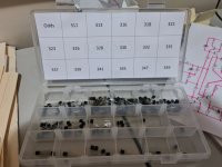
some KSA992F sorted by Hfe. Will do the same for the KSC1845F
Don't forget to sorting and matching trannies at a +-working temps, N- and P-types have slightly varies hFE/temp dependance.
I have played with VAS transistors for a long time and have come to a simple conclusion; use a low Cob transistor in TO126. Then choose at least a 160V transistor (I use the KSC3503 or the 2SC2682) and run them hard, around 10mA or even more. These are low Ic devices, high voltage and speed, and well sinked will run up to 8W. The low Cob minimises compensation issues. Both those transistors run max gain-bandwidth at around 20mA.
Clearly!
driving the VAS base through an emitter follower buffer.
Yes, while VAS is a common emitter stage.
But it's even better to use common base VAS because Cob straightly shunted to gnd.
Common base VAS + common base IPS level shift could be a best for linear amplification until GaNs with ones ns-deadtime will take over the market.
increases loop gain
Yes, but using uncompensated opamp will allow you even more. Just because ot the much higher oncrystal VAS output node impedance. On common PCB you can't achieve so small parasitic leak and so small parasitic capacitance.
Last edited:
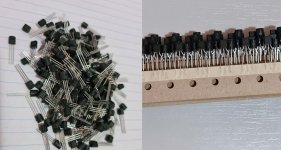
As an aside, my input transistors arrived today. 200 each of genuine Fairchild KSA992 and KSC1845. And they're "F's" so better than 300 gain.
Gotta say I much prefer the loose one's over the taped ones.
Cheers
Q
I have about 3000-3000pcs of KSC1845/KSA992. The order was done in 3 amounts year by year. The most interesting that I can easily create pairs using KSC1845s from the first order, with KSA992s from the last order.
Sajti
I have about 3000-3000pcs of KSC1845/KSA992. The order was done in 3 amounts year by year. The most interesting that I can easily create pairs using KSC1845s from the first order, with KSA992s from the last order.
Sajti
That's a lot of amplifiers Sajti.
Hi Quasi, Your amp is similar to Litchstark I built from the Revisiting ideas from the 1970's thread here.
this amp has dual cascoded VAS and dual KSA992/1845 inputs.
I needed 39pf VAS cap to stabilize the 22 mhz 30v p-p oscillation.
I got 100 of each KSA,KSC and had to use 600 hfe PNP and 400 Hfe NPN. Backing off the current on the NPN differential pair knocked the offset to 18mV. I am running a VAS current of 8mA with KSC3503, KSA1381.
Your amp should be a real good one.
Last edited:
Is this the argument to leave the parallel universe and go for one of the various two-stage second stage (that's three stages actually already, and an impedance stage must follow)?...had to use 600 hfe PNP and 400 Hfe NPN. Backing off the current on the NPN differential pair knocked the offset to 18mV...
And with these high beta's multiple stage are still needed. There's something not right. Hence the initial parallel-thought, I guess.
I'm not convinced if this classical, 50 year old topology will ever find it's optimum configuration.
In the batches of 992's and 1845's used in the front end, I got matched pairs at 600 and 400 hfe with 1 PNP as low as 450. most of the NPN's were 390 to 420 Hfe.
by dropping the NPN pair current , the amp offset moved from 3 volts to 18mV with no change in performance. My amp is DC coupled making the offset far worse then if capacitor coupled.
by dropping the NPN pair current , the amp offset moved from 3 volts to 18mV with no change in performance. My amp is DC coupled making the offset far worse then if capacitor coupled.
Is this the argument to leave the parallel universe and go for one of the various two-stage second stage (that's three stages actually already, and an impedance stage must follow)?
And with these high beta's multiple stage are still needed. There's something not right. Hence the initial parallel-thought, I guess.
I'm not convinced if this classical, 50 year old topology will ever find it's optimum configuration.
Hi MarsBravo,
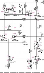
I could probably get away with not using the compound (double) second stage and just run a conventional VAS. I thought I would try the double and minimise the load on the first stage as much as possible.
I first saw this in the schematic* of my old Yamaha Rx-777 receiver and became interested in it. The Yamaha version is after a single ended LTP, but I thought I would try it on the twin.
* Source: Yamaha RX-777 Service manual, Doc 100749, Yamaha Corporation.
Cheers
Q
Attachments
- Home
- Amplifiers
- Solid State
- Second Stage. Paralleling transistors ok?