Hi stanislav1957,
I have miller capacitors in place (C6 & C8) but they do not return to output as you have suggested. Thanks for the idea it will be easy to have that option and compare.
Cheers
Q
I have miller capacitors in place (C6 & C8) but they do not return to output as you have suggested. Thanks for the idea it will be easy to have that option and compare.
Cheers
Q
Cool
Hello, Quasi.
Thank you for the answer. It's too nice.
Ok I understand better for the relay, I had a doubt.
The capacitor is a mistake. In fact in Europe, we write:
1000 µf never 1,000 µf. It's me who skates, laughs !.
Otherwise, I understood perfectly. The approach of the main food, impressive !.
Studies are always very slow, I understand that perfectly.
Work, family and so on. It's the same for me.
I am one of your unconditional Fans. I made all your amplifiers. I take advantage of the confinement to update all my Quasi studies.
Even if your new amplifier, is not a quasi-complementary.
I am impressed by the approach of the future model.
So no worries about study time. I already have a lot to do with all my projects. But I will follow your project with great interest.
Thank you Quasi. Best regards.
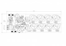
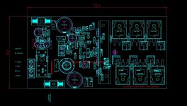
PS. I have attached some realizations of your amplifiers
Hello, Quasi.
Thank you for the answer. It's too nice.
Ok I understand better for the relay, I had a doubt.
The capacitor is a mistake. In fact in Europe, we write:
1000 µf never 1,000 µf. It's me who skates, laughs !.
Otherwise, I understood perfectly. The approach of the main food, impressive !.
Studies are always very slow, I understand that perfectly.
Work, family and so on. It's the same for me.
I am one of your unconditional Fans. I made all your amplifiers. I take advantage of the confinement to update all my Quasi studies.
Even if your new amplifier, is not a quasi-complementary.
I am impressed by the approach of the future model.
So no worries about study time. I already have a lot to do with all my projects. But I will follow your project with great interest.
Thank you Quasi. Best regards.
PS. I have attached some realizations of your amplifiers
Attachments
Aaaah ok. I though you were asking about the value of the capacitors. 😛 So my answer must have been very funny.
Actually I think you are correct. Even here schematics show 1000 and not 1,000 so I need to practice.🙂
I think your layouts are very good - better than mine I think.
Cheers
Q
Actually I think you are correct. Even here schematics show 1000 and not 1,000 so I need to practice.🙂
I think your layouts are very good - better than mine I think.
Cheers
Q
Last edited:
Hello, Quasi.
Sorry for the delay, but I was at sea.
I'm back.
For capacitor values, it's just a question of country actually.
No worries, because I had the same questions about values, so you answered .... cool.
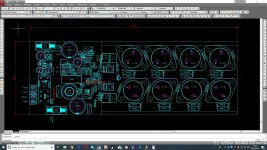
Thanks for my layouts. It's nice and it makes me happy.
I took a long time to find the right route. For me obviously. This does not detract from the design of your routings.
What saved me was the consistency of your patterns, it's great. Then it's copy paste and minor edits.
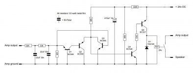
For the Dc Detect I have a problem. I see how it works.
But for me, the relay is in rest contact and opens on detection.
On your diagram the contact is open.
Look on the attachment. I drew the contacts. He is in the rest position. Contacts. 11 and 12 and it passes on 14 in detection.
Because for me, when the amplifier starts, the HP is powered.
It's my logic. Maybe I am wrong about understanding the diagram.
I ran out of IRf452. Exicon France offered me their To3: ECf20n20 and p20. I love the TO3s. Sorry, probably due to my age, laughs !.
I am in the process of assembling N. Mos600 in bridge. This time it's your routing that I'm using for tunneling.
However, I did an automatic switch. If I press on bypass. This cuts the left IN, engages the balun and switches the HP outputs to the hot spots. It's a bit like a gas factory but very efficient.
For the protections, this time, I use the circuits of the Titan 2000.
With us, in France ..... Elektor, it's a whole poem !!!!.
If you need Elektor diagrams, no hesitation, I have all the reviews since day one ..... 1974. Time flies too fast !!!.
I wish you good crafts.
Jacky
Sorry for the delay, but I was at sea.
I'm back.
For capacitor values, it's just a question of country actually.
No worries, because I had the same questions about values, so you answered .... cool.
Thanks for my layouts. It's nice and it makes me happy.
I took a long time to find the right route. For me obviously. This does not detract from the design of your routings.
What saved me was the consistency of your patterns, it's great. Then it's copy paste and minor edits.
For the Dc Detect I have a problem. I see how it works.
But for me, the relay is in rest contact and opens on detection.
On your diagram the contact is open.
Look on the attachment. I drew the contacts. He is in the rest position. Contacts. 11 and 12 and it passes on 14 in detection.
Because for me, when the amplifier starts, the HP is powered.
It's my logic. Maybe I am wrong about understanding the diagram.
I ran out of IRf452. Exicon France offered me their To3: ECf20n20 and p20. I love the TO3s. Sorry, probably due to my age, laughs !.
I am in the process of assembling N. Mos600 in bridge. This time it's your routing that I'm using for tunneling.
However, I did an automatic switch. If I press on bypass. This cuts the left IN, engages the balun and switches the HP outputs to the hot spots. It's a bit like a gas factory but very efficient.
For the protections, this time, I use the circuits of the Titan 2000.
With us, in France ..... Elektor, it's a whole poem !!!!.
If you need Elektor diagrams, no hesitation, I have all the reviews since day one ..... 1974. Time flies too fast !!!.
I wish you good crafts.
Jacky