BH with EL84 is 10%?The 220k is in series. But then ,the feedback ratio is only 3.7% . You can adjust it to 10% by increasing the 150k.
PI is referred to -150V, but what worries me is the low-to-no current part of the cycle.Besides , you need to adjust the operating current . 1.25 ma ×(470k+220k)= 862 volts. To have it about 250v on the anode you need about 1ma.
Has anyone applied current feedback from the secondary of the OT to the cathodes of the power amplifier tubes, to shorten the path?
It's something I?ve never seen in amps, but would shorten the CFB path:
one of the sides of the OT secondary is con nected to the speaker, while the other side (usually grounded) is connected to a 0,1 Ohm resistor, then grounded, then to another 0,1 Ohm resistor. then to the other side of the speaker. This will give two current feedback signals that can be connected to the power amp tubes' cathode bias sensing resistors, giving current feedback on both sides of the PP.
If not clear, I'll post a sketch of it.
Has enyone experienced something like this, together with the BH shunt feedback?
Thanks
Thank you Kay! Do you think a EF86 would do both?
Or maybe something like this after the PI, scaled to the scope, to accomplish gain and swing?
Positive Current Feedback simple Zen amp
Sorry, I don't have any experience with pentode PI's. But my feelings tell me that an EF86 might be too whimpy here. Go for something like EF80, EF94, EF184 or similar.
Best regards!
Best regards!
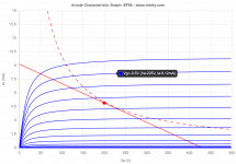
I draw this loadline for the EF86, 430 V B+, 150 V g2, 47 kOhm plate resistor, 4,9 mA. So... I should design the working conditions and the DC load line to have that AC load line.
With an input swinging between -0,5 and -3 V, the output swings between 75 V at 7,5 mA and 327 V at 2,2 mA. It's a gain of 101.
PS
I've found this amp has a EF86 as phase inverter.
https://www.keith-snook.info/amplifier-hifi-schematics/QUAD-II-Schematic.pdf
~ QUAD II Valve Power Amplifier triode cascode phase splitter driver ~
Attachments
Last edited:
Roberto,, if your output tranny is set to 6000 ohm impedance, then in your sketch amp one pair of GU-50 load is 18 kilo ohms and loadline comes very low.
Esa
Esa
Roberto,, if your output tranny is set to 6000 ohm impedance, then in your sketch amp one pair of GU-50 load is 18 kilo ohms and loadline comes very low.
Esa
Hi Esa, the loadline is for one pair only, so the load for the hextet is 2 kOhm Raa.
Roberto,
assuming you bias each GU-50 for 30 mA plate current and Ub will be stable at 870 Vdc, the plate power dissipation will reach a maximum of nearly 60 watts per tube (at about 70% drive). The required drive signal is about 70 Vp for full power. Are you aware of that?
Best regards!
assuming you bias each GU-50 for 30 mA plate current and Ub will be stable at 870 Vdc, the plate power dissipation will reach a maximum of nearly 60 watts per tube (at about 70% drive). The required drive signal is about 70 Vp for full power. Are you aware of that?
Best regards!
Hi Kay,
thanks for the head-up. I used: 280 V on g2, 15V on g3, 870 V on plates, 28 mA at idle (60% of the dissipation) and a load Raa of 6 kOhm. I'm aware I'm over the 40 W dissipation curve, but being off almost 50% of the time, using force ventilation and being bass a non constant source of sound, shouldn't it be acceptable?
As for the needed swing, I've considered to go AB2. I'm searching infos on how positive I can go into AB2 before causing troubles to the tubes. I've seen some amps going around +20 V on g1, and in that scenario if I'm right I would need around 250 Vpp (considering feedback).
Roberto,
it's hard to tell exactly, 'cause in the available datasheets the plate curves end at -25 V at g1. I guess you'll need about -50 V @ g1 for about 30 mA plate current, hence a swing of 70 Vp per side.
Best regards!
it's hard to tell exactly, 'cause in the available datasheets the plate curves end at -25 V at g1. I guess you'll need about -50 V @ g1 for about 30 mA plate current, hence a swing of 70 Vp per side.
Best regards!
Hi Esa, the loadline is for one pair only, so the load for the hextet is 2 kOhm Raa.
800vp on 2k gives 160w.
Thanks Kay,
I've downloaded the following datasheets of the different names of the same tube:
http://wavebourn.com/pyramid-8/GU-50.jpg
http://www.frank.mif.pg.gda.pl/sheets/018/g/GU50.pdf
?????? ??-50. ??????????? ??????????????
https://frank.pocnet.net/sheets/128/e/EL152.pdf
to check (when possible) what shown here:
Loadline calculator for power stages with reactive load - Vacuum Tube Amplifiers - DIY
based on Normal Karen curves and equations:
http://www.normankoren.com/Audio/Tubemodspice_article.html
From there the g1 voltage at idle is -45.69 V, so without any feedback it would be enough to have 65,7 Vp or 131,4 Vpp.
Considering the feedback (as before), this swing has to be multiplied 1,9 times (if my calculations are correct) and so 248,9 Vpp.
PS
I'm attaching this page ( ?????? ??-50. ??????????? ?????????????? ) in pdf format and translated from Russian to English).
Attachments
800vp on 2k gives 160w.
Hi kokoriantz,
i guess you are calculating the power for a SE.
This is a PP, so the formula it's not the swing divided by sqrt(2) then squared and then divided by the load.
So the rms power of a push pull is:
{[(2 x Voltage swing) / sqrt(2)]^2} / Raa =
= {[sqrt(2) x voltage swing]^2} / Raa =
= (2 x voltage swing^2) / Raa = 2 x 640000 / 2000 = 640 Wrms
But it will sag for sure with 1,5 A of current (that's 3 x 500 mA circa), so that power will never be reached.
This datasheet https://tubedata.tubes.se/sheets/118/e/EL152.pdf contains even more info, al least for those who read German 🙂.
Years ago I've seen LS 50 plate curves somewhere in the WWW with the screen @ 300 Vdc which might come closer to what you're planning. But no curves with a positive suppressor at all.
Best regards!
Years ago I've seen LS 50 plate curves somewhere in the WWW with the screen @ 300 Vdc which might come closer to what you're planning. But no curves with a positive suppressor at all.
Best regards!
Hi kokoriantz,
i guess you are calculating the power for a SE.
This is a PP, so the formula it's not the swing divided by sqrt(2) then squared and then divided by the load.
The kokoriantz math also can be applied, but has to be modified as the swing applies to only one primary half. So the load is 500 ohms instead of 2 kOhms. The result will be the same, though 😀.
With my ruler in the plate curve set I've calculated even more.
Anyway, for sure you won't have a supply voltage of 870 Vdc @ full drive, unless you're planning a (regulated) SMPS for that job.
Best regards!
Edit: Btw, what a pity that Hans-Georg (es345) appears to have disappeared. He as an EE has some considerable bunch of experience with this tube and we've had extensive e-mail and phone conversation on his 6 x GU50 bass amplifier in 2012. He also gave valuable hints to another toroid winding shop in Poland, this one even with a German Department located at Munich (Badel).
Last edited:
Thanks Kay,
I will search them, and I will check if in this forum there are some positive g3 curves of the GU50. I've some far memories they are there.
I will translate that EL152 datasheet with google, I've seen a lot of informations there, just need to translate everything.
I will search them, and I will check if in this forum there are some positive g3 curves of the GU50. I've some far memories they are there.
I will translate that EL152 datasheet with google, I've seen a lot of informations there, just need to translate everything.
for sure you won't have a supply voltage of 870 Vdc @ full drive, unless you're planning a (regulated) SMPS for that job.
Best regards!
Thanks again Kay,
do you think it's a reasonable choice to go with a custom SMPS for this amp?
For sure it will, weight-wise 😀 but are there custom designers with reasonable prices for all those voltages? Or maybe just B+ and screens, then go with a thoroid for other small power windings.
...do you think it's a reasonable choice to go with a custom SMPS for this amp?
I wish it were, but I haven't found SMPS's for these voltages so far.
Best regards!
It is indeed. I've written him on various forums, but I've got no replies.Edit: Btw, what a pity that Hans-Georg (es345) appears to have disappeared.
Yes, design in Germany and production in Poland: Ringkerntransformator, Transformatoren, Ringkerntransformatoren | Ringkern, Ringkern-Transformator, 100V-Übertrager - BADEL Elektronik GmbHHe also gave valuable hints to another toroid winding shop in Poland, this one even with a German Department located at Munich (Badel).
PS
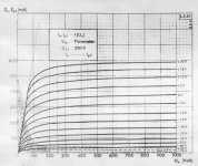
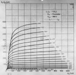
in attachment GU50 curves with g2 at 250 and 300 V.
Attachments
- Home
- Amplifiers
- Tubes / Valves
- 450W bass amp: a sextet of GU50s with shunt¤t feedback