Yes, Ill try, some difficulties maybe with transformers, but schematic rather simple.
http://www.realoldiesradio.com/docs/Altec436/Altec_436C_Detail.pdf
http://www.realoldiesradio.com/docs/Altec436/Altec_436C_Detail.pdf
Hello where could I find LT spice model for kt150 and a hammond transformers and chokes?
As i am.planning to build SE no Feedback amp with them. Also would be very pleased if you could recommend me some good and tryed schematics...thanks alot in advance
As i am.planning to build SE no Feedback amp with them. Also would be very pleased if you could recommend me some good and tryed schematics...thanks alot in advance
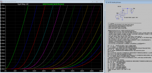
The following KT150 LTSpice model used reference to this some data refered to in this article "Extract Koren Parameters for KT150". Pentode curve looks close but there is no other triode mode curve to compare with, so you see how it turns out with this one.
Code:
**** KT150 ******************************************
* Created on 04/26/2020 12:51 using paint_kip.jar
* [URL="http://www.dmitrynizh.com/tubeparams_image.htm"]www.dmitrynizh.com/tubeparams_image.htm[/URL]
* Plate Curves image file: kt150.png
* Data source link: <plate curves URL>
*----------------------------------------------------------------------------------
.SUBCKT KT150 P G2 G K ; LTSpice tetrode.asy pinout
* .SUBCKT KT150 P G K G2 ; Koren Pentode Pspice pinout
+ PARAMS: MU=10.77 KG1=475.4 KP=28.6 KVB=14.23 VCT=0 EX=1.35 KG2=886.91 KNEE=11.86 KVC=1.66
+ KLAMG=5.513E-4 KNEE2=20 KNEX=30  KNK=-0.044 KNG=0.006 KNPL=50 KNSL=11 KNPR=120 KNSR=29
+ CCG=14P CGP=0.85P CCP=12P RGI=2000.0
* Vp_MAX=500 Ip_MAX=360 Vg_step=5 Vg_start=5 Vg_count=15
* X_MIN=51 Y_MIN=87 X_SIZE=619 Y_SIZE=570 FSZ_X=1296 FSZ_Y=736 XYGrid=false
* Rp=1400 Vg_ac=20 P_max=70 Vg_qui=-30 Vp_qui=300
* showLoadLine=n showIp=y isDHP=n isPP=n isAsymPP=n isUL=n showDissipLimit=y
* showIg1=n isInputSnapped=y addLocalNFB=n
* XYProjections=n harmonicPlot=y dissipPlot=n
* UL=0.43 EG2=225 gridLevel2=n addKink=y isTanhKnee=y advSigmoid=n
*----------------------------------------------------------------------------------
RE1  7 0  1G    ; DUMMY SO NODE 7 HAS 2 CONNECTIONS
E1   7 0  VALUE=  ; E1 BREAKS UP LONG EQUATION FOR G1.
+{V(G2,K)/KP*LOG(1+EXP((1/MU+(VCT+V(G,K))/SQRT(KVB+V(G2,K)*V(G2,K)))*KP))}
RE2  6 0  1G    ; DUMMY SO NODE 6 HAS 2 CONNECTIONS
E2  6 0  VALUE={(PWR(V(7),EX)+PWRS(V(7),EX))} ; Kg1 times KIT current
RE21 21 0 1
E21  21 0 VALUE={V(6)/KG1*ATAN((V(P,K)+KNEX)/KNEE)*TANH(V(P,K)/KNEE2)} ; Ip with knee but no slope and no kink
RE22 22 0 1 ; E22: kink curr deviation for plate
E22  22 0 VALUE={V(21)*LIMIT(KNK-V(G,K)*KNG,0,0.3)*(-ATAN((V(P,K)-KNPL)/KNSL)+ATAN((V(P,K)-KNPR)/KNSR))}
G1   P  K  VALUE={V(21)*(1+KLAMG*V(P,K)) + V(22)}
* Alexander Gurskii screen current, see audioXpress 2/2011, with slope and kink added
RE43 43 K 1G ; Dummy
E43  43 G2 VALUE={0} ; Dummy
G2   43 K  VALUE={V(6)/KG2*(KVC-ATAN((V(P,K)+KNEX)/KNEE)*TANH(V(P,K)/KNEE2))/(1+KLAMG*V(P,K))-V(22)}
RCP  P K  1G     ; FOR CONVERGENCE
C1   K G  {CCG}  ; CATHODE-GRID 1
C2   G P  {CGP}  ; GRID 1-PLATE
C3   K P  {CCP}  ; CATHODE-PLATE
R1   G 5  {RGI}  ; FOR GRID CURRENT
D3   5 K  DX     ; FOR GRID CURRENT }
.MODEL DX D(IS=1N RS=1 CJO=10PF TT=1N)
.ENDS
*$


* The following triode model is derived from pentode model, see above.
* In the triode model, all spice parameters come directly from the pentode model, except for Kg1,
* which for triode-strapped pentodes is derived from pentode's Kg1, Kg2 and Kvc as
*
*    4Kg1Kg2 / ((2Kvc-Pi)(2Kg1+PiKg2))

**** KT150 ******************************************
* Created on 04/26/2020 12:51 using paint_kit.jar 4.7
* [URL="http://www.dmitrynizh.com/tubeparams_image.htm"]www.dmitrynizh.com/tubeparams_image.htm[/URL]
* Plate Curves image file: kt150.png
* Data source link: <plate curves URL>
*----------------------------------------------------------------------------------
.SUBCKT TRIODE_KT150 1 2 3 ; Plate Grid Cathode
+ PARAMS: CCG=14P  CGP=0.85P CCP=12P RGI=2000
+ MU=10.77 KG1=2528.27 KP=28.6 KVB=14.23 VCT=0 EX=1.35
* Vp_MAX=500 Ip_MAX=360 Vg_step=5 Vg_start=5 Vg_count=15
* Rp=1400 Vg_ac=20 P_max=70 Vg_qui=-30 Vp_qui=300
* X_MIN=51 Y_MIN=87 X_SIZE=619 Y_SIZE=570 FSZ_X=1296 FSZ_Y=736 XYGrid=false
* showLoadLine=n showIp=y isDHT=n isPP=n isAsymPP=n showDissipLimit=y
* showIg1=n gridLevel2=n isInputSnapped=y
* XYProjections=n harmonicPlot=y dissipPlot=n
*----------------------------------------------------------------------------------
E1 7 0 VALUE={V(1,3)/KP*LOG(1+EXP(KP*(1/MU+(VCT+V(2,3))/SQRT(KVB+V(1,3)*V(1,3)))))}
RE1 7 0 1G  ; TO AVOID FLOATING NODES
G1 1 3 VALUE={(PWR(V(7),EX)+PWRS(V(7),EX))/KG1}
RCP 1 3 1G   ; TO AVOID FLOATING NODES
C1 2 3 {CCG} ; CATHODE-GRID
C2 2 1 {CGP} ; GRID=PLATE
C3 1 3 {CCP} ; CATHODE-PLATE
D3 5 3 DX ; POSITIVE GRID CURRENT
R1 2 5 {RGI} ; POSITIVE GRID CURRENT
.MODEL DX D(IS=1N RS=1 CJO=10PF TT=1N)
.ENDS
*$
Attachments

6HQ5 Triode
Hi all,
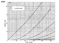
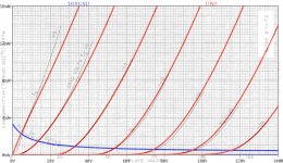
I was looking into 7 pin high-mu RF triodes like the EC97. I found one that looks interesting, the 6HQ5. The data sheet states that it's a sharp cutoff triode (a good thing). Otherwise, it looks similar to the 6HA5, for which there are a couple of models. Does anyone know of an LTspice model for 6HQ5?
I've linked to the data sheet, and attached a screenshot of the plate curves, in case anyone feels like playing with this. I wish I knew how to use those curve tracing tools...
https://frank.pocnet.net/sheets/107/6/6HQ5.pdf
Hi all,
I was looking into 7 pin high-mu RF triodes like the EC97. I found one that looks interesting, the 6HQ5. The data sheet states that it's a sharp cutoff triode (a good thing). Otherwise, it looks similar to the 6HA5, for which there are a couple of models. Does anyone know of an LTspice model for 6HQ5?
I've linked to the data sheet, and attached a screenshot of the plate curves, in case anyone feels like playing with this. I wish I knew how to use those curve tracing tools...
https://frank.pocnet.net/sheets/107/6/6HQ5.pdf
Attachments
So, I am completely new to this. I'm a recent EE grad and have used pspice quite a bit. But how do I implement all the code in these files to model a tube? Could someone point me to a tutorial or something? I've been trying to google and search for it but I don't know how to phrase "implement code for a part in pspice" and get results. I know this isn't probably the right place to post but I'm out of ideas. Thank you! I am trying to play with the code I found for tubes on http://www.duncanamps.com/spice/valves/dmtriodep.inc
Hi all,
I was looking into 7 pin high-mu RF triodes like the EC97. I found one that looks interesting, the 6HQ5. The data sheet states that it's a sharp cutoff triode (a good thing). Otherwise, it looks similar to the 6HA5, for which there are a couple of models. Does anyone know of an LTspice model for 6HQ5?
Code:
* ==============================================================
* 6HQ5 LTSpice model
* Koren model (5 parameters): mean fit error 0.407593mA
* Traced by Wayne Clay on 10/08/2013 using Curve Captor v0.9.1
* from Sylavania data sheet
* ==============================================================
.subckt 6HQ5  P G K
    Bp  P K  I=
+ (0.09448710711m)*uramp(V(P,K)*ln(1.0+exp((2.377015757)+
+ (2.377015757)*(110.3655535)*V(G,K)/sqrt((4.931804002k)+
+ (V(P,K))**2)))/(2.377015757))**(1.15599833)
  Cgk G K 5.7p ; 0.7p added
  Cpk P K 4.0p ; 0.5p added
  Cgp G P 0.72p ; 0.2p added
  Rpk P K 1G   ; to avoid floating nodes
  d3  G K dx1
.model dx1 d(is=1n rs=2k cjo=1pf N=1.5 tt=1n)
.ends 6HQ5
Attachments

So, I am completely new to this. I'm a recent EE grad ...... I am trying to play with the code I found for tubes on http://www.duncanamps.com/spice/valves/dmtriodep.inc
Follow the instruction here: LTSpice and vacuum tube models
These tube models are about 20 years old and used a different tube model than more modern one, so you should try others also to see any better. You can also download power supply designer psud2 here:
PSUD2
Here is a link about the tube modeling and this.

Hi gac23Thank you for the model Adrian, this is awesome!
You are welcome. But which model of mine do you mean?
Thank you so much, Koonw!!! I finally got some working models in PSpice! woohoo!Follow the instruction here: LTSpice and vacuum tube models
These tube models are about 20 years old and used a different tube model than more modern one, so you should try others also to see any better. You can also download power supply designer psud2 here:
PSUD2
Here is a link about the tube modeling and this.
Sorry for the confusion, I took the 811A Tetrode. I am giving a radio amateur course and was hoping I could show the usefulness of neutralization in simulation. I'll see how far I can make in that direction 🙂
Anyone know of a model for type 3S4 (or 1S4)?
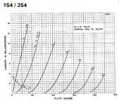
There have been a few threads where people talk about making low voltage line stages using either the 1S4 or 3S4 7-pin mini beam pentode. It looks like you could bias one up with only 48V at the plate, -3V at the grid, 7mA plate current. The heater runs on 1.4V at 100mA.
Data sheets with pentode and triode curves are available:
https://frank.pocnet.net/sheets/049/1/1S4.pdf
https://frank.pocnet.net/sheets/137/3/3S4.pdf
This one includes direct interelectrode capacitances:
http://rtellason.com/tubedata/3S4.PDF
--
Attachments
Anyone know of a model for type 3S4 (or 1S4)?
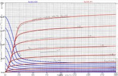
...freshly backed for you, rongon! 😀😀
cheers, Adrian
Code:
*1S4 LTspice model based on the generic tetrode/pentode model from Adrian Immler, version i4f, May 2020
*Important assumptions: heater- = GND
*A version log is at the end of this file
*Params fitted to measured data from a sample by Adrian Immler, May 2020
*fit graphs see adrianimmler.simplesite.com
*This model is an enhancement of Adrians generic triode model to achieve tetrode/pentode behaviour.
*Hence, it is also suitable when the tetrode/pentode is "triode connected".
*Convenient for tetrodes, power beam tetrodes and g3-grounded pentodes.
*Copes secondary emission effect!
*
*                plate (in this model, "anode" means the internal virtual triode anode)
*                | grid2
*                | |  grid1
*                | |  |  cathode
*                | |  |  |
.subckt 1S4.RCi4 P G2 G1 K
.params
*Parameters for the space charge current @ Vg <= 0
+ mu1 = 4.65    ;Main factor for voltage gain @ constant Ia in triode mode
+ ks = 2k25     ;Permeance factor. Has to be readjusted if xs is changed
+ Vg0 = -0.75   ;Offsets the Ia-traces on the Va axis. Electrode material's contact potential
+ kp = 65       ;Mimics the island effect
+ xs = 1.5      ;Determines the curve of the Ia traces. Typically between 1.2 and 1.8
*
*Parameters for an optional space charge current reduction @ Vg > 0
+ kIsr = 0.03   ;Va independable Is reduction, a function of Vg1
+ Rg1i = 1      ;Internal grid1 resistor which causes an extra Is drop when Va approaches zero.
*
*Parameters for assigning the space charge current to Ia and Ig @ Vg > 0 and small Va
+ kB1 = 0.12    ;Describes how fast Ia_virtual drops to zero when Va_virtual approaches zero.
+ radl = 750    ;Differential resistance for the Ia emission limit @ very small Va and Vg > 0
+ tsh = 8       ;Ia transmission sharpness from 1th to 2nd Ia area. Keep between 3 and 20. Start with 20.
+ xl = 1.5      ;Exponent for the emission limit
+ Vctl = 0 f=0  ;Offsets the Ia emission limit trace on the Va axis. f=related Vg1 koeff.
*
*Parameters of the grid-cathode vacuum diode
+ kg1 = 40k     ;Inverse scaling factor for the Va independent part of Ig (caution - interacts with xg!)
+ Vctg1 = 0     ;Offsets the log Ig-traces on the Vg axis. Electrode material's contact potential
+ xg1 = 1.5     ;Determines the curve of the Ig slope versus (positive) Vg and Va >> 0
+ VT = 0.1      ;Log(Ig) slope @ Vg<0. VT=k/q*Tk (cathodes absolute temp, typically 1150K)
*
*Parameters for the caps
+ cg1p  = 0p3   ;according datasheet
+ cg1All= 4p8   ;according datasheet
+ CpAll = 4p    ;according datasheet
+ Cpk  = 1f     ;not mentioned in datasheet
*
*Parameters to enhance the triode model to a pentode model
+ mu2 = 70      ;1/mu2 is the fraction of Vp which together with Vg2i builds the virtual Triode-Anode Voltage
+ kB2 = 0.27    ;Describes how fast Ip drops to zero when Vp approaches zero.
+ Rg2i = 300    ;Internal grid2 resistor. Causes an Is reduction when Ig2 increases while Vp drops
+ fr2 = 120m    ;determines the residual ig2 fraction @ high Va values
+ ftfr2 = 0     ;if fr2 showes a Vg2 dependancy, this can be considered with this parameter
*
*Parameters to mimic the secondary emission (inspired from Derk Reefmans approach)
+ co = 2          ;decribes the crossover region (Ise drop when Va increase). between 0 and 9
+ Vse=18  a=0     ;Va where the sec. emission is strongest. a=related Vg1 coefficient
+ Ise0=0  b=0     ;sec. emission peak current @ Vg=0. b=related Vg1 coefficient
+ Vg2ref = 67     ;Vg2 where the following coeffficients has no influence to the emission effect:
+ c = 0           ;Vg2 coefficient of a
+ d = 0           ;exp Vg2 coefficient of Ise0
+ e = 0           ;Vg2 coeff. of b
*
*Calculated parameters
+ kl = pow(1/(radl*xl*Ild**(1-1/xl)),-xl) ;Reduces the xl influence to the Ia slope @ small Va
+ Ild = sqrt(radl)*1m ;Current where the limited anode a.c. resistance is set according to radl.
*
*Space charge current model
Bggi GG1i 0 V=v(G1i,K)+Vg0 - v(G1,K)*(1-1/(1+kIsr*max(0,v(G1,K)))) ;Effective internal grid voltage.
Bahc Ahc 0 V=uramp(v(P,K)/mu2+v(G2i,K)) ;voltage of the virtual triode anode, hard cut to zero
Bst St 0 V=max(v(GG1i)+v(Ahc)/(mu1), v(Ahc)/kp*ln(1+exp(kp*(1/mu1+v(GG1i)/(1+v(Ahc))))));Steering volt.
Bs Ai K I=1/ks*pow(v(St),xs) ;Langmuir-Childs law for the space charge current Is
*
*Anode current limit @ small Va
.func smin(x,y,n) {pow(pow(x + 1f, -n)+pow(y+1f, -n), -1/n)} ;Min-function with smooth trans.
Ra A Ai 1
Bpl G2i P I=i(Rp) - smin(1/kl*pow(v(P,K)+min(0,Vctl+f*v(G1,K)),xl),i(Rp),tsh);Ip emission limit
*
*Grid model
Rg1i G1 G1i {Rg1i} ;Internal grid resistor for "Ia-reduction" @ Vg > 0
.func Ivd(Vvd, kvd, xvd, VTvd) {1/kvd*pow(VTvd*xvd*ln(1+exp(Vvd/VTvd/xvd)),xvd)} ;Vacuum diode function
Bg1vd G1 K I=Ivd(v(G1,K)+Vctg1-1m*sqrt(v(Ahc)), kg1, xg1, VT) ;Grid-cathode vacuum diode
Bg1r G1i Ai I=ivd(v(GG1i),ks, xs, 0.8*VT)/(1+kB1*v(Ahc));Is reflection to grid when Va appr. zero
Bs0 Ai K I=ivd(v(GG1i),ks, xs, 0.8*VT) - 1/ks*pow(v(GG1i),xs) ;Compensates neg Ia
*@ small Va and Vg near zero
*
*additional model parts necessary for a pentode
Rg2i G2 G2i {Rg2i}
Rp P A 1
Bg2r G2i A I=i(Ra)*((1-frg2())/(1+kB2*max(0,v(P,K))) ) ; Va dependable ig2 part, reflected from the plate
Bg2f G2  A I=i(Ra)*frg2() ; Va independable ig2 part. Not to lead this current over Rg2i improves convergence
.func frg2() {fr2*exp(ftfr2*(v(G2,K)-45))}
*
*model for secondary emission effect
*nomalizing function nf(sh) ensures that the peak of y=x*(1-tanh(sh(x-1)) is always at x=1 while sh=0..9
.func nf(z) {609m/z + 293m + 107m*z - 5.71m*z*z}
.func sh() {pow(co,2)} ;results in a more linear control of the cross over region with the param co
Bsee G2 P I=min(Ise()*nf(sh())*xf()*(1-tanh(sh()*(nf(sh())*xf()-1))) / (nf(sh())*(1-tanh(sh()*(nf(sh())-1)))),i(Rp)-i(Bpl))
.func Ise() {smin(uramp(Isef() - bf()*v(G1,K)),0.98*i(Rp),2)} ;avoides neg. Iplate caused by strong sec. em.
.func xf() {v(P,K)/(1m+uramp(Vse-af()*v(G1,K)))}; moves the sec emission peak to the wanted voltage Vsep
.func af() {a + c*(v(G2,K)-Vg2ref)}
.func Isef()   {Ise0 * exp(d*(v(G2,K)-Vg2ref))}
.func bf()  {b + e*((v(G2,K)-Vg2ref))}
*
*Caps
C1 G1 P {cg1p}
C2 G1 K {(cg1All-cg1p)/2} ;As this model does not consider the ambient as further electrodes for parasitic caps,
;best way is to assume this " g1 to all" cap as it would be half to cathode and half to g2 (after substraction of cg1p).
C3 G1 G2 {(cg1All-cg1p)/2}
C4 P K {cpk}
C5 P G2 {cpAll-cpk-cg1p}
.ends
*
*Version log
*i1 :Initial version
*i2 :Pin order changed to the more common order "P G2 G1 K" (Thanks to Markus Gyger for his tip)
*i3 :residual ig2 @ large Va introduced; 2nd emission effect introduced;
;Va indep. grid current parts no longer lead over internal grid resistors for better convergence
*i4 :to improve convegence, the Ia reduction @ pos Vg is no longer done by Rg1i. Instead, kIsr introduced
;Furthermore, ks and Vg0 are set directly, as rad and Vct turned out to be usefull for triodes only
*i4f :Major bug fixed. Tube works now also when Cathode not grounded (for cathode follower and the like)
Attachments
Adrian, have you finally developed some kind of software for tube modeling, or you just do it by hand?
Do your model support different screen voltages? What about remote cutoff tubes?
Do your model support different screen voltages? What about remote cutoff tubes?
Last edited:
Adrian, have you finally developed some kind of software for tube modeling, or you just do it by hand?
Do your model support different screen voltages? What about remote cutoff tubes?
Hi rankot,
It‘s a pitty... 🙁 Due to lack of deeper programming knowledge, I‘m still running without a spice fitting tool. My workflow is as terrible to use like the moon landing vehicle was to fly. But thanks a lot of training, Armstrong mastered a perfect landing - and I also get some routine 😉 .
Yes, my pentode copes different srceen voltages (and hence, also the triode mode).
Remote cutoff tubes are made by two different winding pitches of the control grid - so in principal, a remote cutoff tube can be modeled by two tubes in parallel. Its a lot of iterative work, so I guess it is more important to have a very convenient tool than a super accurate model approach.
All the best, Adrian
...freshly backed for you, rongon! 😀😀
cheers, Adrian
Thanks Adrian, that's fantastic!
Going to give it a spin now....
- Home
- Amplifiers
- Tubes / Valves
- Vacuum Tube SPICE Models