Maybe bug report
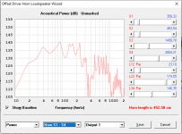
All looks fine when computing output from the main screen. However, the power in the wizard looks very strange. Maybe I am using Hornresp wrong?
The record is made from an older version of Hornresp.
All looks fine when computing output from the main screen. However, the power in the wizard looks very strange. Maybe I am using Hornresp wrong?
The record is made from an older version of Hornresp.
Attachments
hello
I know this is an addon to a very old post BUT.... is there any way to run HORNRESP in W10 64bit Machine?
Thanks
eduardo
I know this is an addon to a very old post BUT.... is there any way to run HORNRESP in W10 64bit Machine?
Thanks
eduardo
HR runs on all my Windows 10 pc/laptops no matter if it's 32 or 64 bit. I have been forced on one 64 bit laptop to put HR in the default spot of C:/Hornresp. All other computers, I put HR in the Programs folder.
Hornresp Update 5070-200425
Hi Everyone,
The limitation reported in Post #10653 has now been removed.
Stay safe,
David
Hi Everyone,
The limitation reported in Post #10653 has now been removed.
Stay safe,
David
If Vrc & Lrc is a cylinder cross section, then how does Vrc = 33.56L and Lrc = 20.32 cm equal S1 = 1651.61, S2 = 1651.61, and L12 = 20.32cm
Hi BP1Fanatic,
Not sure I understand the problem 🙂.
Cylinder cross-sectional area = Vrc / Lrc = 33.56 * 1000 / 20.32 = 1651.57 cm^2 (rounded to 2 decimal places).
If S1 = 1651.57 cm^2, S2 = 1651.57 cm^2 and L12 = 20.32 cm, the volume of the segment is 1651.57 * 20.32 / 1000 = 33 .56 litres, the same as for Vrc, as expected.
Am I missing something here?
Stay safe,
David
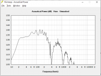
All looks fine when computing output from the main screen. However, the power in the wizard looks very strange.
Hi Mårten,
My reply to 'Booger weldz' in Post #10655 applies to your case also 🙂.
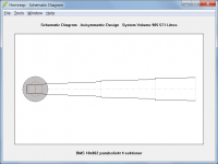
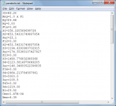
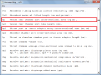
You have specified a stepped segment design, as shown in Attachment 1.
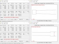
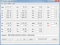
In the main calculation it is simulated as shown in Attachment 2.
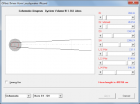
In the Loudspeaker Wizard it is simulated as shown in Attachment 3.
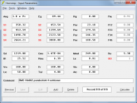
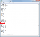
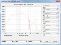
Not that it affects the results, but the thing I don't understand is how you managed to end up with more than two decimal places for the exported segment area and length values, as shown in Attachment 4.
Stay safe,
David
Attachments

When simulating an offset driver horn is there a way of the driver entry point specified by AP1 and LP to have a flare?
Hi kipman725,
Not without adding a new input parameter to specify the cross-sectional area at the outlet end of the port tube. This would require changes to so many parts of the program that it is simply not a practical option.
(A throat adaptor on a standard Nd design can be flared because S1 becomes the outlet area).
Stay safe,
David
Click on Ap1 to Ap to switch from round to square.
???
Since when?
🙂.
Hi David, can you include the value for "Path" be included in the BOXPLAN export option in your next update for Hornresp?
Hi Brian,
It should already be there, as shown in the attachment.
Stay safe,
David
Attachments
Hi Brian,
It should already be there, as shown in the attachment.
Stay safe,
David
It's included in the initial Import process. However pressing F6 in the Loudspeaker Wizard doesn't reset the value for "Path" in the sim to the new value in the import file.
???
Since when?
🙂.
All I did was switch from Ap1 to Ap. I was trying to model a BR, but HR wouldn't let switch the function. I had to do a FLH/BP6P/CH to get the function to work.
Attachments
Hi Mårten,
My reply to 'Booger weldz' in Post #10655 applies to your case also 🙂.
Thanks David!
I suggest that you either remove the wizard for stepped simulations, or limit the functionality to allow everything except changing areas.
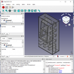
This is because I am generating the hornresp record from my cad software. I attached a screenshot 🙂Not that it affects the results, but the thing I don't understand is how you managed to end up with more than two decimal places for the exported segment area and length values, as shown in Attachment 4.
David
Attachments
I suggest that you either remove the wizard for stepped simulations, or limit the functionality to allow everything except changing areas.
What I really want simulate is filling in section 1. Can I reduce the resonances at 66 Hz and 99 Hz?
However pressing F6 in the Loudspeaker Wizard doesn't reset the value for "Path" in the sim to the new value in the import file.
Thanks for the additional information. The Path value will refresh in the next update.
All I did was switch from Ap1 to Ap.
Yes, but I still don't understand what you mean by "switch from round to square" 🙂.
I was trying to model a BR, but HR wouldn't let switch the function.
That's because Ap1 refers to either a throat adaptor in the case of a normal horn, or a throat port in the case of an offset driver horn. It is not applicable to a standard bass reflex system, where Ap is used instead.
Attachments
I suggest that you either remove the wizard for stepped simulations, or limit the functionality to allow everything except changing areas.
That's unlikely to happen. Too much work went into implementing the functionality in the first place, to now throw it all away 🙂.
This is because I am generating the hornresp record from my cad software.
Ah, now I understand. Mystery solved. Thanks.
What I really want simulate is filling in section 1.
In that case, I suggest you approximate the stepped segment system with an unstepped system. Make the unstepped radius at S2 equal to the average of the two stepped radii at S2, and the unstepped radius at S3 equal to the average of the two stepped radii at S3. This means that S2 then becomes 1342.40 cm^2 and S3 becomes 2386.24 cm^2.
Can I reduce the resonances at 66 Hz and 99 Hz?
Yes, but including the absorbent filling material in segment 2 rather than in segment 1, will have a more pronounced effect.
Attachments
Last edited:
In that case, I suggest you approximate the stepped segment system with an unstepped system. Make the unstepped radius at S2 equal to the average of the two stepped radii at S2, and the unstepped radius at S3 equal to the average of the two stepped radii at S3. This means that S2 then becomes 1342.40 cm^2 and S3 becomes 2386.24 cm^2.
Yes, but including the absorbent filling material in segment 2 rather than in segment 1, will have a more pronounced effect.
Thanks David!
Of course the filling should go into section 2.
Too much work went into implementing the functionality in the first place, to now throw it all away 🙂.
Another reason for keeping it, is that it enables the user to experiment with all sorts of different setups 🙂.
Attachments
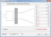
It's because you have specified stepped segments. When the Loudspeaker Wizard is used with the stepped segments option selected, all the segments will be cylindrical apart from the last one, regardless of the profile specified. This limitation is necessary to avoid having to increase the number of area sliders in the wizard. In your case, the last segment is also cylindrical because you have the S4 slider set to Auto.
...... or limit the functionality to allow everything except changing areas.
That's unlikely to happen. Too much work went into implementing the functionality in the first place, to now throw it all away 🙂.
My other suggestion maybe? If the reason for not simulating stepped segments is the number of sliders, you can disable the area sliders if the simulation is stepped.
- Home
- Loudspeakers
- Subwoofers
- Hornresp