Is there a way to model a multi segment horn that starts with a conical (or other profile) horn segment and ends with a Tractrix profile in the last segment?
Hi chromenuts,
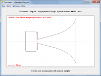
It can only be done by specifying a throat adaptor in front of the tractrix horn.
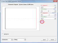
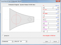
Attachments 1 and 2 show an example tractrix horn with a conical adaptor.
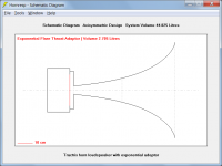
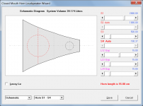
Attachments 3 and 4 show the same tractrix horn with an exponential adaptor.
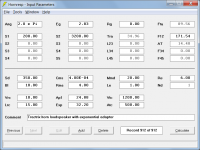
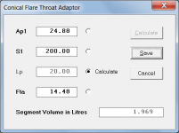
For a conical adaptor, double-clicking on the Ap1 or Lp (Con) text box in Edit mode opens a wizard which enables the angle of the adaptor to be matched to the throat angle of the tractrix horn, as shown in Attachment 5.
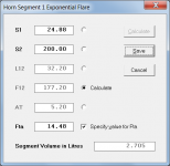
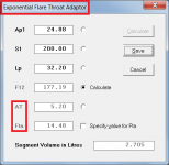
In the next release it will be possible to do the same for an exponential adaptor, but at the moment it is necessary to specify the required angle in the standard Horn Segment Wizard tool, using a "dummy" segment to represent the adaptor, as shown in Attachment 6. The wizard S1 and L12 values can then be manually copied to the Ap1 and Lp (Exp) throat adaptor text boxes on the main input parameters window.
Stay safe,
David
Attachments

Hi David
The Oris horns are the model 200. They are supposed to be based on a “modified” Tractrix profile. According to what I have read on this subject the “modified” part appears to have more to do with how they are terminated at the mouth.
Looking at the side view, it looks as if the horns have been terminated before the tractrix curve reached 90 degrees, and then fitted with a small flange. Since the tractrix is relatively close to the exponential curve for part of its length, you may be able to simulate these horns using a couple of exponential segments. It may be possible to trace the curve by taking a photo from the side (at a reasonably large distance to avoid optical distortion) and assume constant wall thickness. Or you could take the photo into a image editor and overlay various curves from Hornresp and see how close you get.
Thanks for the feedback everyone.
It’s been a hectic week with everyone home 24/7.
Thank you so much for that detailed explanation David. I felt kind of foolish having to ask. I knew there must be a way to do it. I just couldn’t wrap my head around how.
I’m hoping to get back to my models in the next few days so I can try creating some different conical adapters for the horns. I picked up a second pair of the B&C 8pe21 that someone had never used so I am very interested in exploring both an offset dual driver adapter and a multi-entry variant with either the Radian or Dynaudio drivers.
Here is a brief summary of the theory behind creating cardioid directivity, and how to achieve it using a resistive U-frame in Hornresp.Yes please!
Attachment #1: The most straightforward(analytical anyways) method for creating cardioid directivity is to co-locate and combine the outputs from a monopole source and a dipole source. By varying the relative magnitude of the two sources, the combined source directivity can be varied between dipole, cardiod, and monopole.
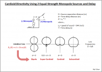
Attachment #2: The most common practical method for creating cardioid directivity is to combine the outputs from two monopoles(equal magnitude but one inverted) spaced apart from each other and one source delayed relative to the other. Crunching through the summation math, an equation for the combined directivity appears that is very similar to the one for the combined monopole/dipole method. With the distance between the sources fixed, the combined source directivity can be manipulated simply by adjusting the time delay. Traditionally, the delay is fed to the inverted source resulting in the directivity pattern “pointing” in the direction of the non-inverted source. Note that the directivity pattern is only obtained for low frequencies where the wavelength is much greater than the source separation distance.
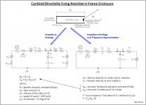
Attachment #3: It doesn’t take too much imagination to realize that a U-frame can be used to create a passive implementation of the delayed two source method. The radiation coming from the backside of the U-frame is naturally inverted relative to the forward direct radiation from the woofer. At low frequencies, the air in the frame (or tube) acts like a compliance. If an acoustic resistance is placed at the vent exit, the radiation exiting the vent will be delayed by a time proportional to the compliance of the air in the tube and the acoustic resistance placed at the exit (ie the RC time constant). Uniformly stuffing the tube also delays the vent radiation at low frequencies, but the delay will not be constant with frequency and the front and rear radiation magnitudes will diverge.
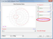
Attachment #4: Overlaying the directivity on a decibel scale for super-cardiod thru sub-cardiod, it is easy to see what Olson, Bauer and others determined analytically. Although it doesn't have a null at 180deg, the super-cardioid provides the most “uni-directional” response overall. If a ratio of delay to source separation distance(d/D) of 0.8 is targeted, a reasonably uniform directivity pattern results across the bass octaves.
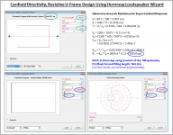
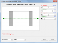
Attachment #5: Using the Hornresp U-Frame Loudspeaker Wizard, the appropriate resistance to place at the exit of the tube can be calculated using the dimensions shown on the Schematic. The path length between acoustic centers is the source separation distance D. The U-Frame tube area is Sd. The volume of the tube can be calculated from the area and length. Then it is a simple matter of back-calculating the required acoustic resistance to get a delay equal to 0.8 * D.
Hornresp doesn’t currently have a facility to define an acoustic resistance at the exit of a tube. But, you can use a thin layer of filling to emulate the effect. The filling density is given in Rayl/m, and you can specify values up to 99999. Using as thin a filling layer as possible at the exit of the tube such that the product of filling density(Rayl/m) and thickness (m) gives you the required acoustic resistance (Rayl). In the example, the thickness is set at 0.6cm = 0.006m, and a filling density of 84000 resulting in an acoustic resistance of 0.006 * 84000 = 504 Rayl. If for a given design you can't achieve the desired acoustic resistance, increase the length of the filling layer until you can.
Attachments


Last edited:
Here is a brief summary of the theory behind creating cardioid directivity, and how to achieve it using a resistive U-frame in Hornresp.
Hi bolserst,
Beautiful work, as always. Many thanks!
Kind regards,
David
PS - On working though the given example I noticed a very minor and probably quite obvious typo in the fifth attachment, but just in case anyone is confused, the value of 5.493e-6 shown for Cab in the Rav formula should be the same as the value calculated for Cab on the line above, that is, 5.493e-7.
In the example, the thickness is set at 0.6cm = 0.006m, and a filling density of 84000 resulting in an acoustic resistance of 0.006 * 84000 = 504 Rayl. If for a given design you can't achieve the desired acoustic resistance, increase the length of the filling layer until you can.
It goes without saying that the next release of Hornresp will be able to do all of this automatically, if so required... 🙂.
Attachments

Hornresp Update 5070-200422
Hi Everyone,
CHANGE 1
When the Loudspeaker Wizard is used with a system having an offset driver and an offset port, passive radiator or closed stub, changing L23 in a three segment system now automatically adjusts L34 to keep the total length constant. Similarly, changing L34 in a four segment system automatically adjusts L45 to keep the total length constant. Adjusting L34 in a three segment system or L45 in a four segment system changes the length of the final segment and the overall total length of the system. Also, S3 in a three segment system can now be switched from Manual to Auto, as can S4 in a four segment system. Attachments 1 and 2 refer.
CHANGE 2
In the Multiple Entry Horn Loudspeaker Wizard, changing L12 in a two, three or four segment system now automatically adjusts L23 to keep the total length constant, changing L23 in a three or four segment system automatically adjusts L34 to keep the total length constant, and changing L34 in a four segment system automatically adjusts L45 to keep the total length constant. Adjusting L23 in a two segment system, L34 in a three segment system or L45 in a four segment system, changes the length of the final segment and the overall total length of the system.
CHANGE 3
In the Loudspeaker Wizard, filling material now remains visible when the acoustic centres of a dipole system are shown. Posts #10613 and #10616 and Attachment 3 refer.
CHANGE 4
When the Horn Segment Wizard is used with an exponential flare throat adaptor, double-clicking on the Cir label now changes the parameter from Cir to Fta so that the wizard can calculate both the throat entry half-angle AT and the mouth flare tangent angle Fta of the adaptor. Attachment 4 refers.
CHANGE 5
When the Loudspeaker Wizard is used with a direct radiator in a U-frame open baffle, the Fr and Tal values required to achieve cardioid directivity in a resistive system can now be automatically calculated by selecting the Filling option and then double-clicking on the Manual label below the Fr1 and Tal1 slider controls. Double-clicking on the default Rs parameter label changes the displayed filling material parameter from specific acoustical resistance Rs in mks rayls, to acoustical resistance Ra in acoustical ohms. Attachment 5 refers. My thanks to 'bolserst' for making the details of his method available for use in Hornresp.
BUG FIX 1
In the Loudspeaker Wizard, dipole system acoustic centres were not being hidden when the Escape key was pressed. The form was closing instead. This problem has now been fixed. Posts #10613 and #10616 refer. My thanks to 'bolserst' for reporting the bug.
BUG FIX 2
In the Loudspeaker Wizard, the dipole system directivity pattern would change if the Output 1 or Output 2 power response option was selected. This problem has now been fixed. Posts #10613 and #10616 refer. My thanks to 'bolserst' for reporting the bug.
BUG FIX 3
When the Loudspeaker Wizard was used with a one segment SH2 system, slider S2 was incorrectly shown as having a Manual/Auto option. For a two segment SH3 system, slider S3 incorrectly had the option, and for a three segment SH4 system, double-clicking on the unmarked S2 slider label would incorrectly invoke the option. These problems have now been fixed.
Stay safe,
David
Attachments
I have a question on Lrc, what is meant by average length? Should that be the distance between two longest boundaries of the rear chamber or something else? I am attempting to account for some resonance closer to the pass band than expected in a few designs. I noticed the value has an effect on few different aspects of the design once I strated poking around further. Any guidance would be appreciated.
Hi, first post here, but months of using Horn Resp with many thanks!
I noticed quite a few times when entering loudspeaker wizard with red 's' inputs used(segment mode), the system will periodically remove any mouth to throat segment CSA differences. Then once you leave the wizard section you'll be left with a different system volume even if you only entered to add stuffing or set an OD(things which clearly don't change volume of the cabinet. If you never enter schematic you'll never know this and could really miss some details once this is wooden.
an example would be:
consecutive segments as
(s)throat-(s)mouth (L)length
44-133 22
153-97 22
45-33 12
33-33 25
once you leave wizard(actually it occurs upon entering), you get this example:
44-153 22
153-97 22
97-33 12
33-33 25
this is in OD but I'm not sure its exclusive to that.
thanks for everything, and then thanks again
When the Loudspeaker Wizard is used with a direct radiator in a U-frame open baffle, the Fr and Tal values required to achieve cardioid directivity in a resistive system can now be automatically calculated by selecting the Filling option and then double-clicking on the Manual label below the Fr1 and Tal1 slider controls.
'bolserst' has identified a limitation in the above new functionality, due to my misinterpretation of the contents one of the formulas in the worked example he provided. The results currently only apply to a U-frame that has the same cross-sectional area as the driver diaphragm. This limitation will be removed in the next release - hopefully it should be available in the next day or so.
I have a question on Lrc, what is meant by average length?
Hi Red Five,
It is very much a judgement call on the part of the user. By way of background, I originally decided to include "average length" in the Lrc description 50 years ago, when I was trying to simulate a Klipschorn loudspeaker and needed to determine the distance from the rear side of the diaphragm to the "back" of the sealed wedge-shaped chamber behind the driver.
The chamber is actually modelled in Hornesp as a cylinder of volume Vrc and length Lrc. The cylinder cross-sectional area is given by Vrc / Lrc.
Kind regards,
David
I noticed quite a few times when entering loudspeaker wizard with red 's' inputs used(segment mode), the system will periodically remove any mouth to throat segment CSA differences.
Hi Booger weldz,
Hopefully the post linked below helps to clarify why this is happening.
https://www.diyaudio.com/forums/subwoofers/119854-hornresp-959.html#post5810006
Kind regards,
David
Hi Booger weldz,
Hopefully the post linked below helps to clarify why this is happening.
https://www.diyaudio.com/forums/subwoofers/119854-hornresp-959.html#post5810006
Kind regards,
David
Got it, thanks David👍🏻
Hi David, can you include the value for "Path" be included in the BOXPLAN export option in your next update for Hornresp? I'm looking at how the value for "Path" can impact the power response of MLTL designs, and it looks like the impact can be pretty noticeable in some cases.
When simulating an offset driver horn is there a way of the driver entry point specified by AP1 and LP to have a flare rather than modeled as a cylinder?
Hi Red Five,
It is very much a judgement call on the part of the user. By way of background, I originally decided to include "average length" in the Lrc description 50 years ago, when I was trying to simulate a Klipschorn loudspeaker and needed to determine the distance from the rear side of the diaphragm to the "back" of the sealed wedge-shaped chamber behind the driver.
The chamber is actually modelled in Hornesp as a cylinder of volume Vrc and length Lrc. The cylinder cross-sectional area is given by Vrc / Lrc.
Kind regards,
David
If Vrc & Lrc is a cylinder cross section, then how does
Vrc = 33.56L and Lrc = 20.32 cm
equal
S1 = 1651.61, S2 = 1651.61, and L12 = 20.32cm
on the Schematic Diagram when using the Nd function?
I do notice the circles when using the OD function.
When simulating an offset driver horn is there a way of the driver entry point specified by AP1 and LP to have a flare rather than modeled as a cylinder?
Click on Ap1 to Ap to switch from round to square.
- Home
- Loudspeakers
- Subwoofers
- Hornresp