Because some years ago i also tested a dac kit with PCM1794 and i like it a lot the sound of this chip i was thinking to come back and give it a try again.
I remember it sounded very good with Lm49713 in I/V position but a bit hard to tame them as they are very fast opamps.
That's why i want to ask @pachy : why did you choose to introduce between dac board and Raspberry that Jlsounds USB to I2S receiver? You could feed the dac with I2S directly from Raspberry.
Last edited:
JLsounds XMOS provides galvanic isolation which eliminates common noise which is produced by the Raspberry Pi or its PSU and even more important is that it hosts oscillators for reclock of the signal which results in significantly reduced jitter compared to the Raspberry Pi's own I2S which is just not good enough for high quality audio.Because some years ago i also tested a dac kit with PCM1794 and i like it a lot the sound of this chip i was thinking to come back and give it a try again.
I remember it sounded very good with Lm49713 in I/V position but a bit hard to tame them as they are very fast opamps.
That's why i want to ask @pachy : why did you choose to introduce between dac board and Raspberry that Jlsounds USB to I2S receiver? You could feed the dac with I2S directly from Raspberry.
If you are still not convinced see a more detailed explanation here: The Raspberry Pi: Audio out through I2S | Dimdim's Blog
@pachy,
which Input and output signal to / from Jlsounds are you using
which Input and output signal to / from Jlsounds are you using
congratulations
very clever choice of modules
would you please describe change In sound (If there was) when you just change stock OPA to OPA1612 and OPA2132
Interested to know how do you connect XMOS board and pcm1794 board using just 2 wires
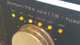
I am using the S/PDIF output of JLSounds because I wanted to retain digital input switching capability by the AK4113 on the PCM1794 board, which switches between the stock s/pdif coax connector which I relocated on the rear panel of my enclosure, stock toslink (also relocated) and the s/pdif from the JLSounds board. You can find the hidden third S/PDIF input on the first two pins on the Amanero header of the PCM1794 board.@pachy,
which Input and output signal to / from Jlsounds are you using
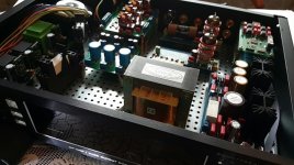
What do you mean by the "right" transformer? Power supply transformer is 2x15VAC + 2x9VAC R-core transformer from Audiophonics(or ebay, aliexpress). For the Raspberry and JLSounds XMOS I have a separate 2x6VAC transformer before linear regulators, one winding is used for the Pi and the other one supplies the part of the JLSounds (with reclock / after galvanic isolation), the USB part of JLSounds is supplied from the USB connection to the Raspberry.
@pachy,
what a fast response!
Yes, i need an 15V-0-15V + 2*9V Transformer.
I did not find the correct one (at audiophonics) etc.
From china, there are a lot of different ones...
what a fast response!
Yes, i need an 15V-0-15V + 2*9V Transformer.
I did not find the correct one (at audiophonics) etc.
From china, there are a lot of different ones...
That is the one I have. You can also use two toroidal or PCB type transformers that you can find in your country. One with 2x15 or 15-0-15, and one with 2x9VAC windings. Check at Reichelt or TME, both will ship to Austria.
@pachy,
thanks for your help.
Ordered one (same as yours).
If all arrived, i will done some measurements (missing in this thread!) and post the results here.
edit:
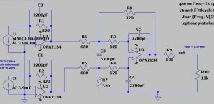
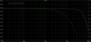
Done some simulations in LTSpice (I/V & LPF)
have a nice day!
thanks for your help.
Ordered one (same as yours).
If all arrived, i will done some measurements (missing in this thread!) and post the results here.
edit:
Done some simulations in LTSpice (I/V & LPF)
have a nice day!
Last edited:
@pachy,
thanks for your help.
Ordered one (same as yours).
If all arrived, i will done some measurements (missing in this thread!) and post the results here.
edit:
Done some simulations in LTSpice (I/V & LPF)
have a nice day!
Any chance that you could share the LT Spice file? I would like to do simulations for my ES9038Q2M board.
My DAC arrived from China.
First impressions, the AD827 gone really hot, changed for safety reason to 5532.
Sadly, the display does not shows any information.....
All voltages are correct.
Except the display the DAC is working.
If i have more time i will begin to measure the device.
First impressions, the AD827 gone really hot, changed for safety reason to 5532.
Sadly, the display does not shows any information.....
All voltages are correct.
Except the display the DAC is working.
If i have more time i will begin to measure the device.
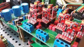
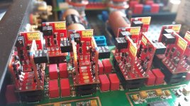
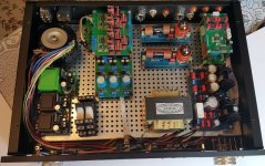
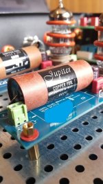
DAC PCM1794 AK4118. Slight change. Replacing opam with discrete in my DAC.
PROJEKT "PANA-MERA" COMBO " - OPAM / LAMPA , 2-u systemowy przetwornik - Audiomaniacy
PROJEKT "PANA-MERA" COMBO " - OPAM / LAMPA , 2-u systemowy przetwornik - Audiomaniacy
I don't know if OP is still modifying his or her PCM1794 dac. But the mod that did the most was the CCS mod on pin 'something or the other' (forgot the number) that I got from the DDDac thread. It's a -40mA CCS that's there in place of the resistor to ground if I can remember correctly. I made it on a piece of protoboard. It's just a trimmer, a transistor and a resister or 2.
Hi .
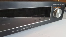
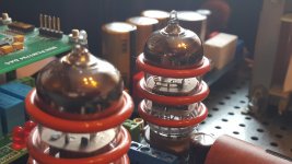
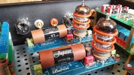
It took some time and some small progress to make a dual system DAC with the use of PCM 1794 and vacuum tubes.

It took some time and some small progress to make a dual system DAC with the use of PCM 1794 and vacuum tubes.
Attachments
- Home
- Source & Line
- Digital Line Level
- Improving a cheap chinese PCM1794 DAC