*...bias voltage is 13v to 15v across the emitter resistors." that is almost impossible!
I built both channels individually. Both are showing the same voltages (13v to 15v)
Good morning, I can't adjust my AX11 bias. In the tests the lamp remains on and biases with 350mV and each emitter. I've already changed all the transistors, i installed a 5k pot (in place of 4k7), checked for short circuits, but it didn't work, rotate the pot but do not change bias.
I made some measurements:
Differential pair: BC546
BxC=1,95V, 2,03V
CxE=1,31V, 1,37V
BxE=595mV, 594mV
BC546
BxC=2,70V
CxE=630mV
BxC=2,07V
BC639 and BC640
BxC= 2,03V, 1,95V
CxE= 1,37V, 1,31V
BxE= 594mV, 595mV
BD139 and BD140
BxC= 1,98V, 2,07V
CxE= 2,65V, 2,71V
BxE= 630mV, 639mV
BC517
BxC=2,72V
CxE=3,38V
BxE=661mV
2SC5200 and 2SA1943
BxC=2,65V, 2,68V
CxE=3,30V, 3,35V
BxE=672mV, 694mV
I forgot to measure mpsa92, if necessary I will do the measurement.
To help is welcome, thank you.
(I'm testing the amplifier on the right)
BC 517 is this transistor in right position, haven't you rotated it 180 degrees? it should be mounted with flat side to the heatsink.
I built both channels individually. Both are showing the same voltages (13v to 15v)
13V over 2x0,2Ohm is 13/0.4=32,5A of current. what are the values of your emiter resistors,and how do you measure it? have you connected input gnd to psu GND?
BC 517 is this transistor in right position, haven't you rotated it 180 degrees? it should be mounted with flat side to the heatsink.
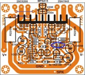
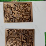
I did it according to this layout, installed BC517 inverted. Is the pcb correct?
Attachments

13V over 2x0,2Ohm is 13/0.4=32,5A of current. what are the values of your emiter resistors,and how do you measure it? have you connected input gnd to psu GND?
That resistor is R22 so 13V is 57.2A. No way that is right.
I did it according to this layout, installed BC517 inverted. Is the pcb correct?
Hello brother, yes this PCB layout correct. Only one change, 2k2 resistance change with 1k or 820R or 680R.
I made that PCB on https://www.diyaudio.com/forums/sol...mate-fidelity-amplifier-1055.html#post5515173
Changed resistance value mark below
Regards
Attachments
That resistor is R22 so 13V is 57.2A. No way that is right.
he said "resistors",so I thought two o series. nevertheless,the point is the same-no way ...
Sir,
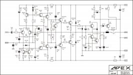
I have built two individual channels of APEX AX14P according to the Circuit and PCB attached here with. After fixing the Head Sink, shorted Input to Power Ground, disconnected the Speakers, and applied +45/-45V . Measured the voltage at Emitter Resistors by adjusting the POT., the voltage is varying from 13V to 15V . The Output Transistors are also getting hot within few seconds. I have thoroughly verified all the components and its positions (pin to pin) though I bought new ones.
After that, I have changed the R16 (1k) Resistor at the Base of Q10 (BD139) with 470 Ohms. The Bias voltage is remained same (13v to 15v) and there is not heat at Output Transistors.
It is present situation of my Amplifier.
I am here with attaching the images of Circuit Schematics and also PCB made by me for your ready reference.
Sir, Please kindly help me in trouble shooting and I am very enthusiastic to complete the Amplifier.
Thanking you, Sir.
Attachments

at what points on schematic have you connected voltmeter when you tried to measure emiter-resistor voltage?
13V over 2x0,2Ohm is 13/0.4=32,5A of current. what are the values of your emiter resistors,and how do you measure it? have you connected input gnd to psu GND?
My amplifier is AX14P. The values of Emitter Resistors are 0.33 Ohms/5W. I connected Input Ground to Power Supply Ground. Connected DMM Negative Proble to Power Supply Ground; and Positive Probe at across the Emitter Resisters (R23 and R24)
Hi Siva, have you connected the signal ground and power ground.
Yes. I did.
Sir,
I have built two individual channels of APEX AX14P according to the Circuit and PCB attached here with. After fixing the Head Sink, shorted Input to Power Ground, disconnected the Speakers, and applied +45/-45V . Measured the voltage at Emitter Resistors by adjusting the POT., the voltage is varying from 13V to 15V . The Output Transistors are also getting hot within few seconds. I have thoroughly verified all the components and its positions (pin to pin) though I bought new ones.
After that, I have changed the R16 (1k) Resistor at the Base of Q10 (BD139) with 470 Ohms. The Bias voltage is remained same (13v to 15v) and there is not heat at Output Transistors.
It is present situation of my Amplifier.
I am here with attaching the images of Circuit Schematics and also PCB made by me for your ready reference.
Sir, Please kindly help me in trouble shooting and I am very enthusiastic to complete the Amplifier.


so,you have measured output symmetry and not voltage across the emiter resistor.
voltage across emiter-resistor is measured actually across the emiter resistor - on its two ends.
SGND point from schematic MUST BE CONNECTED TO PSU-GND,than you will not have 13-15V and finally relay will click to connect output.
voltage across emiter-resistor is measured actually across the emiter resistor - on its two ends.
SGND point from schematic MUST BE CONNECTED TO PSU-GND,than you will not have 13-15V and finally relay will click to connect output.
Hi Siva, have you connected the signal ground and power ground.
Sir, I have connected Input to the Power Ground.
so,you have measured output symmetry and not voltage across the emiter resistor.
voltage across emiter-resistor is measured actually across the emiter resistor - on its two ends.
SGND point from schematic MUST BE CONNECTED TO PSU-GND,than you will not have 13-15V and finally relay will click to connect output.
Yes Sir. I have measured the voltage at the junction of two Resistors not at two ends of single Resistor. Today I will measure according to your suggestion and intimate the result.
Thanking you.
Yes Sir. I have measured the voltage at the junction of two Resistors not at two ends of single Resistor. Today I will measure according to your suggestion and intimate the result.
Thanking you.
I am attaching a PDF with approximate voltages that you should expect with a +-45V rails. These voltages are all measured with reference to ground. Please compare your boards to this schematic. Again these are approximate. Yours may vary slightly but should be close.
Attachments
Hi Siva, have you connected the signal ground and power ground.
Sorry. I told you Yes in earlier post. I didn't connect to Signal Ground and Power Ground.
that is what you should do,than dc offset will decrease from 13-15V to about 30mV or so. than measure voltage across emiter-resistor to achieve about 40-50mA idle current.
- Home
- Amplifiers
- Solid State
- 100W Ultimate Fidelity Amplifier