Is it possible that the diodes are printed with the wrong orientation on the pcb?
Just removed and traced them according to the schematic and it seems so to me.
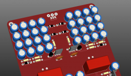
I use a pcb from the first group buy.
Hi.
These diodes are in series with 100R each. In PCB the diodes and resistors switch places but their orintation and operation remain intact. Diodes are placed in the correct polarity, don't worry.
I see now, just the position if R9 is reversed with D3, in comparison with the schematic. I wait for some BAV21 diodes the next days and will check again.
Preamp update
Preamp test showing distortion vs. output level. Tested for a span of 0V to 4V peak to peak.
YouTube video link-> THD Vs. LEVEL - PEECEEBEE PREAMP
Although I am controlling the THD with a multi-turn trimpot, it can be done with a simple 10K single-turn linear pot as well.
____________
From video description:
First test is at minimum THD level, second at maximum, and third at medium.
At minimum THD setting the harmonics are very low and does not vary too much in respect to output level. At maximum setting the harmonic content is very high and follow output level very linearly. The same is true for medium level but harmonics are lowered in amount.
Notice that in all cases, the predominant harmonic is the second one. Everything after the second is at a much lower level, and beyond the fourth harmonic there is almost nothing present.
No averaging used in the spectrum analyzer.
____________
Next update will show THD vs Load impedance, clipping performance and listening tests.
As one can guess, it is a full BJT symmetrical design with MJE transistors at output, total bias current 25mA. I thing it will drive both 32ohm and 600ohm headphones with ease. Will come with next update shortly.
Stay tuned! 🙂
Changed the diodes to BAV21 and everything looks fine now!
As I used the previous ones on my V4 peeceebee, I assumed that it would be no problem.
Thanks Shaan for your support.
As I used the previous ones on my V4 peeceebee, I assumed that it would be no problem.
Thanks Shaan for your support.
Changed the diodes to BAV21 and everything looks fine now!
As I used the previous ones on my V4 peeceebee, I assumed that it would be no problem.
Thanks Shaan for your support.
Errr... I have been using 1N4148 for all my V4 builds powered from 35V, and have never encountered such a problem, unless there was some problem with the diodes themselves, which I guess is what happened in your case.
I'm glad to know you got it working. BAV is totally fine in place of 4148.
 🙂
🙂I used the same 1n4148 in my V4 no problem. But I can not explane why I had problem with the V4H. Anyway I am waiting for a 2X42V tensformer to finish my build.
Hmm. The choice for BAV over 4148 is only for operation at higher than 50V rails. You were testing with only 31V rails where 4148s should be no problem. Strange indeed.
Do let us know your thoughts after listening to the v4hs. 🙂
Do let us know your thoughts after listening to the v4hs. 🙂
shaan,
any boards left. i need 2 if available.
Rick G.
Hi Rick.
A few boards are available. Will send you invoice shortly.
Thanks for coming back. 🙂
Payment sent.
Thank you again for doing all this. This will most likely be my last attempt at doing it right due to my eyes (AMD).Looking forward to it.
Rick G.
Thank you again for doing all this. This will most likely be my last attempt at doing it right due to my eyes (AMD).Looking forward to it.
Rick G.
Payment sent.
Thank you again for doing all this. This will most likely be my last attempt at doing it right due to my eyes (AMD).Looking forward to it.
Rick G.
Shipping the boards tomorrow.
Thank YOU for giving it another push despite everything, sir.

Looking forward to release of preamp! A preamp will be nice compamy for my V4H. Keep up the good!
Preamp test showing distortion vs. output level. Tested for a span of 0V to 4V peak to peak.
YouTube video link-> THD Vs. LEVEL - PEECEEBEE PREAMP
Although I am controlling the THD with a multi-turn trimpot, it can be done with a simple 10K single-turn linear pot as well.
____________
From video description:
First test is at minimum THD level, second at maximum, and third at medium.
At minimum THD setting the harmonics are very low and does not vary too much in respect to output level. At maximum setting the harmonic content is very high and follow output level very linearly. The same is true for medium level but harmonics are lowered in amount.
Notice that in all cases, the predominant harmonic is the second one. Everything after the second is at a much lower level, and beyond the fourth harmonic there is almost nothing present.
No averaging used in the spectrum analyzer.
____________
Next update will show THD vs Load impedance, clipping performance and listening tests.
As one can guess, it is a full BJT symmetrical design with MJE transistors at output, total bias current 25mA. I thing it will drive both 32ohm and 600ohm headphones with ease. Will come with next update shortly.
Stay tuned! 🙂
Looking forward to make this preamp pcb , can you share pdf for own etching pcb
Looking forward to make this preamp pcb , can you share pdf for own etching pcb
Hi Vikram.
Thanks a lot for your interest. The PCBs will be available through diyaudio group-buy only.
Ground breaker for my dual mono setup
Hi !
As I'm having a lot of spare time home these days (you know why I guess),
I've started working again on my PCBs.
One of them if completely populated and locked on its heatsink
and its PSU working well, but not both interconnected yet.
The PSU (Cresnet SMPS) doesn't have 0V and Earth connected, and I guess I should not get them interconnected with my setup.
I intend to build a dual mono enclosure, and I'm aware of the Earth / ground issue connection to the heatsinks.
Could you please provide a schematic of the ground breaker circuit I need for my setup ?
Did I make myself clear ? Thanks in advance
JMK
Hi !
The PSU (Cresnet SMPS) doesn't have 0V and Earth connected, and I guess I should not get them interconnected with my setup.
I intend to build a dual mono enclosure, and I'm aware of the Earth / ground issue connection to the heatsinks.
Could you please provide a schematic of the ground breaker circuit I need for my setup ?
Did I make myself clear ? Thanks in advance
JMK
Maybe I won't have any oscillation issue as my current setup has power amplifier (and preamp) completely ground separated and behind an AC mains isolation transformer.
JMK
Hi !
As I'm having a lot of spare time home these days (you know why I guess),
I've started working again on my PCBs.
One of them if completely populated and locked on its heatsink
and its PSU working well, but not both interconnected yet.
The PSU (Cresnet SMPS) doesn't have 0V and Earth connected, and I guess I should not get them interconnected with my setup.
I intend to build a dual mono enclosure, and I'm aware of the Earth / ground issue connection to the heatsinks.
Could you please provide a schematic of the ground breaker circuit I need for my setup ?
Did I make myself clear ? Thanks in advance
JMK
Maybe I won't have any oscillation issue as my current setup has power amplifier (and preamp) completely ground separated and behind an AC mains isolation transformer.
JMK
Hi Jean.
You can connect the loop breaker the way shown in the attachment. You can either use bridge rectifier modules or just four 15-20A diodes and make the connections as shown.
Be safe and bests.
Attachments

Hi Jean.
You can connect the loop breaker the way shown in the attachment. You can either use bridge rectifier modules or just four 15-20A diodes and make the connections as shown.
Be safe and bests.
OK, one more question: do I need TWO breakers (one for each PSU),
as I have 2 PSUs (dual mono setup) in my enclosure ?
Thanks a lot !!
JMK
OK, one more question: do I need TWO breakers (one for each PSU),
as I have 2 PSUs (dual mono setup) in my enclosure ?
Thanks a lot !!
JMK
Yes, one breaker is needed for each PSU.
- Home
- Group Buys
- PeeCeeBee V4H GB