Sounds like a BP4 to me. The space between the cone and the plate is the ported volume. The diameter of the hole and the thickness of the plate would be your port. Atc and Vtc can be used to change the ported volume.
Last edited:
Hi all,
need some help on how to model...
... a driver mounted in a sealed box, with a plate completely covering the face of the driver, and with a hole in the plate.
Plate thickness, or length of hole could range fro 1mm to 15mm.
Basically, like placing a driver in a MEH, but without any horn.
I'm thinking it might be worthwhile to understand how this simple test bed models, to learn what compression ratios, hole lengths, and T/S parameters work best...for eventual placement in a MEH.
Oh, and if there is a way to model changing the volume of space between the driver cone and the plate, that would be helpful too.
Thanks, mark
take your model for that driver in a sealed box and then start constructing an Nd horn in front of it. start for example with S1=S2=Sd/2 and Con12 = thickness of the plate. For accuracy you need to model the air trapped betweeen the con and the plate as a throat chamber, Vtc, Atc.
Thx BP1Fanantic, and thanks nc535,
So with the Nd horn method, what are good values for Vtc and Atc?
I figure a decent Vtc guess might be in the zipcode of 1/2 to 2/3 of a 'volume taken up by driver' spec ??
I can always measure rice I guess....
But what is a good Atc value? It's supposed to be average cross section area, right?
How would you equate that to Sd?
Ok, got rid of the lazy's and rice worked.
Also found the Driver Front Volume tool, which agreed with the rice .
So no worries with Vtc 🙂
Still uncertain what to use for Atc....
thx
Also found the Driver Front Volume tool, which agreed with the rice .
So no worries with Vtc 🙂
Still uncertain what to use for Atc....
thx
If I'm following you, Atc will be next to nothing, i.e. just the volume trapped by the plate is too much if wanting to max out BW, with the hole [CR] governing how flat it is. For example just maxed out [5 octaves] an AE TD18H and with a 3:1 CR/1.8 cm, HR 'says' Atc = a whopping 20 cc!
GM
edit: Actually, in retrospect it turned out to be more accurate at Vtc/10,000 = 27.031 cc
GM
edit: Actually, in retrospect it turned out to be more accurate at Vtc/10,000 = 27.031 cc
Last edited:
edit 2: Obviously this is just an extreme example as no way can an 18" driver move but a tiny fraction of a mm before bottoming out against the plate, so no power handling beyond tiny fractions of a W, so let this spec be your guide.
Vtc is a volume = Atc * cone depth
So measure cone depth, panel to dustcap, and do the math. Cone depth is easy to measure; Atc is otherwise hard to estimate.
Vtc is the important parameter. Atc can be a swag. Confirm that by simulating a range of values a noting the sensitivity.
When Vtc is so large as to limit the BW, you can fabricate a "volume plug" to displace air under the cone, leaving just enough room for excursion. I doubt Vtc is going to be problematic for a woofer but it can help trying to squeeze a few hundred more hertz out of a synergy mid struggling to get XO past 1.5 khz.
Speaking of excursion, your panel must be thick enough and routed out to allow for surround movement and for the cone itself near the surround....
Vtc is a volume = Atc * cone depth
So measure cone depth, panel to dustcap, and do the math. Cone depth is easy to measure; Atc is otherwise hard to estimate.
Vtc is the important parameter. Atc can be a swag. Confirm that by simulating a range of values a noting the sensitivity.
When Vtc is so large as to limit the BW, you can fabricate a "volume plug" to displace air under the cone, leaving just enough room for excursion. I doubt Vtc is going to be problematic for a woofer but it can help trying to squeeze a few hundred more hertz out of a synergy mid struggling to get XO past 1.5 khz.
Speaking of excursion, your panel must be thick enough and routed out to allow for surround movement and for the cone itself near the surround....
Thanks Jack,
Yep, Vtc, being volume, was very clear.
Atc, being an average area, had me questioning 'average of what areas'.
I was getting Atc by averaging dust cap area and Sd, which wasn't too far from the divide Vtc by dustcap that you suggest.
I do see Atc doesn't appear to have a big effect on the sims.
Another yep re routing recess...
Pict below is one from beginning synergy tries...
I'm starting another synergy attempt...hopefully pretty mobile with a detachable secondary tractrix flare (ala k-402)
Attachments

Thank GM, the exercise I'm working on is just a test jig, to help better learn how limited bandwidth drivers might behave jammed onto the walls of synergy horns.
hey your blocking the corner pocket!
i wonder if anyone has ever recycled a pool table slate into a loudspeaker??
i wonder if anyone has ever recycled a pool table slate into a loudspeaker??
hey your blocking the corner pocket!
i wonder if anyone has ever recycled a pool table slate into a loudspeaker??
😀 funny !
Hmm, maybe......seen several large slate baffles in my time [marble, granite too] due to where I live, but never occurred to me that they may have been from pool, snooker, etc., tables.
GM
GM
How is space being modeled? Is it possible to see the boundaries of the selected space in relation to the speaker/horn in schematic view? Perhaps you could sketch a few common scenarios to show the positioning in a 3D drawing to clear up whether the speaker/ horn is in front of the boundary, or does the boundary start at the mouth.
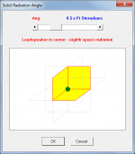
Extreme case: what if I want to knock out a hole in one wall near each bottom corner and put the horns in the adjacent room, with the mouth flush with the walls and floor? Now those horns are radiating into 1/8th space, but the boundary of the 1/8th space starts at the mouth, as the horns themselves are not in the room.
Extreme case: what if I want to knock out a hole in one wall near each bottom corner and put the horns in the adjacent room, with the mouth flush with the walls and floor? Now those horns are radiating into 1/8th space, but the boundary of the 1/8th space starts at the mouth, as the horns themselves are not in the room.
Thank GM, the exercise I'm working on is just a test jig, to help better learn how limited bandwidth drivers might behave jammed onto the walls of synergy horns.
You're welcome!
Understood, though thought you were just interested in basic BP4 theory, i.e. driver centered in a single 'port'. Oh well, maybe of some use to others not yet 'practiced in the art' 😉.
GM
Extreme case:
Consider the size of the WLs involved and if the horn's intended BW is high enough to move it into pi space, then 'mold' into the corner with appropriate cavity damping to get a 'close enough' 1/2 pi space loading up to point of beaming.
GM
Hi there, I am happily using Hornresp for the past years,, this evening I ran into this problem, maybe the creator himself would know how to solve it. I think it probably has to do with the last record name I put in, I figured the error is in the hornresp record database file. A clean dat file works fine
I cant access the old one.
this is the message

I cant access the old one.
this is the message
How is space being modeled? to clear up whether the speaker/ horn is in front of the boundary, or does the boundary start at the mouth.
Strictly speaking, the boundary starts at the mouth, however for an actual practical horn loudspeaker, provided that the dimensions of the radiator and distance from the walls are small compared to the wavelength, the loading conditions will not be unduly compromised. This is why the classic Klipschorn bass corner horn design works so well.
The Hornresp simulation model assumes a point source, as shown in the attachment.
Attachments
maybe the creator himself would know how to solve it.
I would need a copy of the corrupted Hornresp.dat file to diagnose and fix the problem. The file can be posted as an attachment if the extension is changed from .dat to .txt. Alternatively, you could send me a copy via email.
- Home
- Loudspeakers
- Subwoofers
- Hornresp