OK, here is the link: Fusion 360 sample project
It says the model is empty but it lets you to open it in Fusion 360 - then there are the prepared splines.
It says the model is empty but it lets you to open it in Fusion 360 - then there are the prepared splines.
Ah, the units. I have to figure that out - right now it's not at all clear to me why it wants the input in centimeters (?). OK, so be it, now it should be correct - updated scale
I do not know if it is a problem of scale, whenever I import a cloud of points with Fusion does not place it at the origin, I have to look for it through space. Now with mobile, I don't have access to the PC, tomorrow I look at it.
Now it is right size and it's a piece of cake to make it solid.
I turned off the timeline capture, not sure if needed.
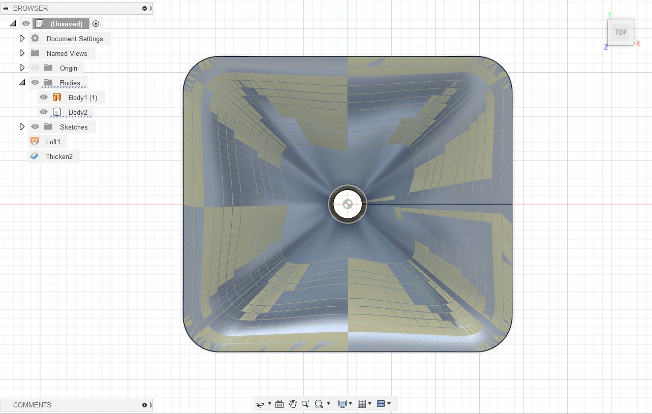
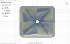
Go to SURFACE workspace, from CREATE menu select LOFT.
Choose the splines from bottom to top, one by one, in the right order. This creates a surface shape via these curves. Be sure not to choose a point along the line, but the whole line. It turns dark blue when you are in the right spot for selection.
After choosing the last click OK.
Then choose the new loft from the component tree, open CREATE menu again and choose THICKEN. Add the thickness you want to outside of the model.
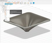
Job done. Now i got 6mm thick solid horn which i can further work with to add mounting holes, driver mounting flange etc.
Mabat, you are a hero!
I turned off the timeline capture, not sure if needed.
Go to SURFACE workspace, from CREATE menu select LOFT.
Choose the splines from bottom to top, one by one, in the right order. This creates a surface shape via these curves. Be sure not to choose a point along the line, but the whole line. It turns dark blue when you are in the right spot for selection.
After choosing the last click OK.
Then choose the new loft from the component tree, open CREATE menu again and choose THICKEN. Add the thickness you want to outside of the model.
Job done. Now i got 6mm thick solid horn which i can further work with to add mounting holes, driver mounting flange etc.
Mabat, you are a hero!
Attachments
Last edited:

I will release it soon. This file will be simply among the output files the tool creates (i.e. the coordiantes of surface points in text format). I have it ready, just have to write some documentation...
Then there's a Fusion 360 Add-In (a Python script in fact) that opens this file and creates all the splines automatically. All will be included in the upcoming version.
Actually, I'm sure that by employing Fusion API, the loft feature and whole surface could be created automatically just by selecting the input file. I'm only not that far yet - maybe someone else. And thanks Pasi for the instructions! Perfect. This is somethig I hoped for from the beginning. Now we have it.
Last edited:
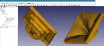
Anyway, I'am using Freecad to prepare real 3D model for manufacturing (3D print, CNC...).
It's quite simple: import STL, convert to mesh, convert mesh to solid and then use boolean operations with another solids to create flange, mounting holes etc....
It's quite simple: import STL, convert to mesh, convert mesh to solid and then use boolean operations with another solids to create flange, mounting holes etc....
Attachments
Last edited:
Curve Lofting Guide Attached
The other thing I found was that the original surface and the thickened one were not exactly the same when overlaid.
Mabat that is exactly what I spent a long time trying to reverse engineer from the mesh file, if you could release that it would be awesome.I can easily export the surface coordinates in a text file that can be imported as spilnes in Fusion 360 (I already have a custom add-on for that). Would that be useful? Is it possible to create a smooth surface and then a solid body from that?
I have attached zipped pdf guide of what I did to make a solid by thickening or by cutting a mould out of a block as before. I have tried to include all the steps to help someone who is not very familiar with Fusion 360.So I will make this available. I hope someone would then present a procedure that everyone can reproduce - I'm not experienced in CAD modeling. That would be great. What about some "guide" curves for this loft feature? I can export various curves of the surface.
It works either way, only meshes need to specifically have the design history turned off to work on.I turned off the timeline capture, not sure if needed.
I found that if I chose any more than 6mm for the thicken then fusion crashed.Job done. Now i got 6mm thick solid horn which i can further work with to add mounting holes, driver mounting flange etc.
The other thing I found was that the original surface and the thickened one were not exactly the same when overlaid.
🙂Mabat, you are a hero!
Attachments
pet007: Of course, but then you are limited by the STL resolution. I don't say it is not enough for e.g. 3D printing. There may be situations where the precision of a smoothly (i.e. mathematically) constructed surface comes beneficial.
Do you mean the original STL and the "lofted" one from the splines? That's what needs to be checked of course. The two might be slightly different, that's almost expected - that's where some perpendicular guide curves may help. I will let the user export those as well.The other thing I found was that the original surface and the thickened one were not exactly the same when overlaid.
Last edited:
No that was the difference between the lofted splines and a thickened version of lofted splines, I didn't have the mesh version of that waveguide to compare to. If you can point me to the configuration or an stl model I can overlay them and see if there are any differences.
Ah, of course. I'm in hurry now, better to let it for more relaxed time... I will definitely return back to this. Thanks so far.
I would expect the "boundary patch" feature in the "surface" tab to be the most effective way. Select all. It creates a surface from the mesh/splines. Then "thicken".
You can set the tolerances yourself in "conditions" in the thicken window. Alternatively do a surface offset and combine the two surfaces into a solid using "boundary fill"
You can set the tolerances yourself in "conditions" in the thicken window. Alternatively do a surface offset and combine the two surfaces into a solid using "boundary fill"
When I had a WG surface I needed to turn into a waveguide (I did that by importing STL and converting to BREP), then I created another surface outside, then lofted the edges at the mouth and throat and then stitched the four surfaces together. Then there is a solid with the exact inner surface and you can do whatever you want with it.
Last edited:
That thickness issue on Fusion360 after 7mm thickness seems to be caused by the throat angle. Due to that, it starts to self intersect when thickening, so need to work around that by doing this in smaller sections there. Or extending the first and last layer and then lofting the outsides together.
I could export curve sets for two surfaces some (defined) distance apart if that would help.
That could do it nicely. I presume we could specify that thickness we want? After that it would be just build 2 surfaces on Fusion, add top and bottom. Convert to solid. Job done.
Edit: Do we need all those spots as they are splines? I'd imagine some of them could be reduced, assuming that the script can do it?
The number of spots just as the number of splines/layers is completely up to the user - this is set in the horn definition file by the parameters "Mesh.*Segments". It may need different values for BEM simulation and for Fusion export but that's also completely up to the user (could have separate files for different purposes).
Yes, the distance for thickness would be configurable as well.
Yes, the distance for thickness would be configurable as well.
- Home
- Loudspeakers
- Multi-Way
- Acoustic Horn Design – The Easy Way (Ath4)